
Attention! Depending on the power plant, the inner CV joint can be ball bearing or roller «tripod». AT SHRUS «tripod» instead of six balls, three rollers are installed on the sprocket, located at an angle of 120°relative to each other.
1. Remove the drive shaft.
2. Clamp the removed drive shaft in a vise, having previously installed protective plates on the vise jaws.
3. Mark where the edge of the CV joint collar is located on the drive shaft in order to subsequently install the collar in its original place.
Be careful not to damage the protective lacquer that covers the drive shaft when marking.
4. Cut the steel clamps of both cuffs with side cutters and remove them. Slide the collar onto the shaft. If necessary, knock it down with a punch.
Outer CV joint
Removing
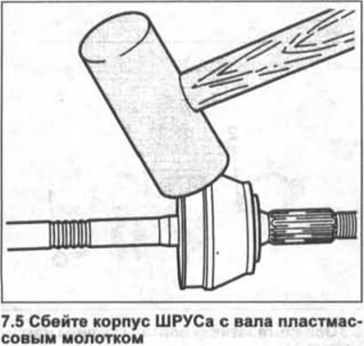
5. Knock the CV joint housing off the shaft with a plastic hammer (see illustration).
6. Remove the retaining ring with 3 suitable needle nose pliers (see illustrations 6.0, 6.0a).
7. Remove thrust ring 4 and disk spring 5 from the drive shaft (see illustrations 6.0, 6.0a).
8. Remove the CV joint collar from the shaft.
Installation
9. Slide the clamping collar that is mounted on the small diameter collar on the drive shaft onto the drive shaft.
10. Install a new seal on the shaft if the old one is damaged or its rubber has become brittle.
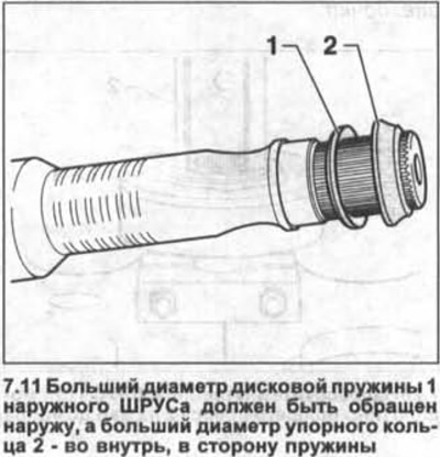
11. Install disc spring and thrust washer on drive shaft. The larger diameter of the disk spring 1 of the outer CV joint should face outward, towards the splined shank, and the larger diameter of the thrust ring 2 should face inward, towards the spring (see illustration).
12. Install a new circlip into the groove on the drive shaft.
13. Stuff the outer CV joint with a plastic hammer onto the shaft until it stops so that it locks onto the retaining ring.
14. Stuff into CV joints «eternal» lubricant such as LM47 Liqui Moly. Half of the lubricant is stuffed into the cuff, and the other half into the hinge.
15. Put the cuff on the CV joint housing and secure it with a new clamping collar.
16. Tighten the stainless steel clamps for attaching the CV joint collars to the drive shaft using the HAZET 1847 pliers.
If the clamps are tightened in any other way, the required tightening torque of the clamps will not be ensured (see illustration).
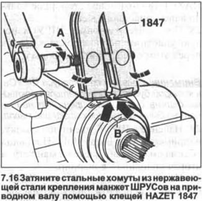
17. Install the HAZET 1847 pliers so that their edges go into the corners, as shown by arrows B in illustration 7.16. With the jaws in this position, tighten clamping bolt A with a torque wrench to 25 Nm. At the same time, the tightening of the steel clamp will also be performed.
Attention! The thread of the hole for the clamping bolt on the pliers should be widened and the bolt should be easily screwed in. If necessary, apply MoS2 molybdenum grease to the threads.
18. Install the assembled drive shaft in place.
Internal CV joint
Removing
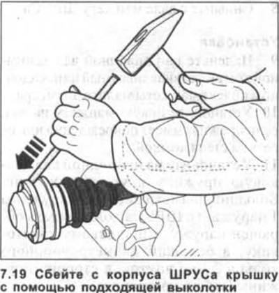
19. Internal CV joint VL 100/107. Knock off the cover from the CV joint housing using a suitable drift (see illustration).
20. Remove the sealing gasket 18 from the CV joint (see illustration 6.0).
21. Remove the circlip 19 with suitable needle nose pliers, e.g. HAZET 1847-61 (see illustration 6.0).
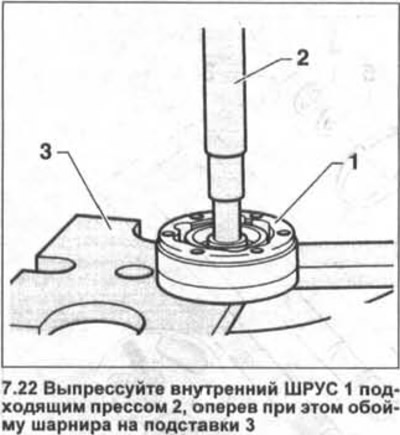
22. Press out the inner CV joint 1 with a suitable press 2, while resting the hinge holder on the supports 3 (see illustration).
Installation
23. Put on the drive shaft the clamping collar mounted on the landing belt of the cuff of small diameter.
24. Install a new seal on the shaft if the old one is damaged or its rubber has become brittle.
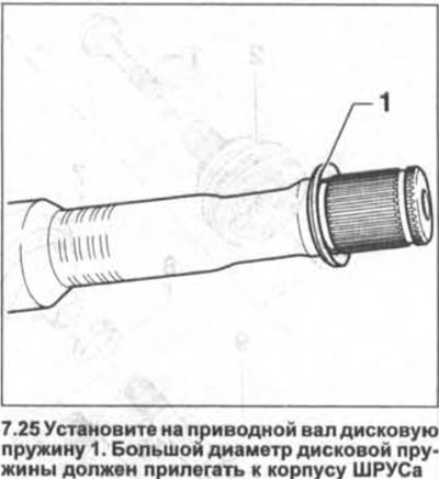
25. Install disk spring on drive shaft 1. Large diameter disk spring must be against CV joint housing (see illustration).
26. Press the inner CV joint 1 with a suitable press 2 onto the shaft until it stops (see illustration).
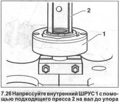
Attention! The chamfered side of the inner diameter of the CV joint must face the thrust collar on the drive shaft.
27. Use HAZET 1847-61 needle nose pliers to install a new circlip into the drive shaft groove.
28. Glue a new gasket to the CV joint housing, having removed the protective foil from it before that.
Attention! The surface of the CV joint housing, to which the gasket will be glued, must be degreased. It must be free of grease or oil residue.
29. Stuff in the CV joint «eternal» lubricant such as LM47 Liqui Moly. Half of the lubricant is stuffed into the cuff, and the other half into the hinge.
30. Put the cuff on the CV joint housing, having previously applied VW-D454 300 A2 sealant to the sealing surfaces.
31. Fasten the cuff with new clamps, which are tightened with special pliers, for example, HAZET 1847.
32. CV joint VL 100/107 Put a new cover on the CV joint housing.
33. Install the drive shaft in place.
Internal CV joint «tripod»
Removing
34. Remove the CV joint housing from the drive shaft.
35. Remove the circlip 15 with suitable needle nose pliers, e.g. HAZET 1846, from the drive shaft (see illustration 6.0a).
36. Remove the sprocket with rollers from the drive shaft using a suitable press.
37. Remove the CV joint collar from the drive shaft.
Installation
38. Put on the drive shaft the clamping collar mounted on the landing belt of the cuff of small diameter.
39. Install a new seal on the shaft if the old one is damaged or its rubber has become brittle.
40. Slide the roller sprocket with the chamfered side of the bore onto the drive shaft and press it in with a suitable press until it stops.
Attention! Before doing this, lubricate the splines on the shaft and in the sprocket bore.
41. Install a new circlip in the drive shaft groove.
42. Pack half of the grease from the repair kit into the CV joint and into the CV joint housing.
43. Put the cuff on the CV joint and secure it with new clamps.
44. Clamp the fastening collars on the cuff landing bands.
Attention! When installing the SHRUS «tripod» AAR 3300i, make sure that the holes for the bolts with which the CV joint is attached to the flange on the gearbox are aligned.
45. Reinstall the drive shaft.
Visitor comments