



2. Unscrew the plug of the check valve, remove the plug and its sealing gasket 11 (Fig. 3.53).
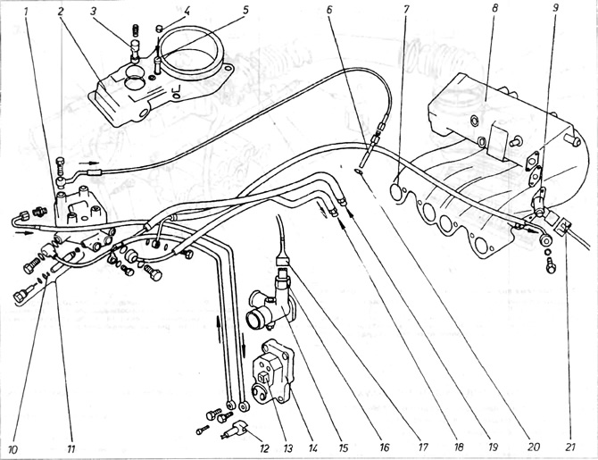
Figure 3.53. Gasoline injection system
1 - fuel distributor; 2 - flow meter; 3 - control piston; 4 - plug; 5 - mixture composition adjustment bolt; 6 - forsuika; 7 - Drive manifold hole; 8 - drive (underwater) manifold; 9 - cold start valve; 10 - adjusting washers; 11 - pressure regulator; 12 - plug; 13 - connection; 14 - engine preheating valve; 15 - cooling system nipple; 16 - Thermal time switch; 17 - connection; 18 - return blue pipe, 19 - feed pipe; 20 - O-ring type sealing ring; 21 - connection of the starting valve.
3. Then remove the piston O-ring and the second O-ring in order.
[The original text can be found at: vwmanual.ru]
4. When installing, put on new sealing rings and make sure that all adjusting washers are in place. The number of washers (gaskets) installed is decisive for the operating pressure in the system. If for some reason the pressure in the system seems abnormal, it is necessary to check the pressure at a Volkswagen service station, where the necessary tools for checking the pressure in the system should be available. The station will determine the number of washers (gaskets) required for correct pressure adjustment, if such adjustment is necessary.
Visitor comments