



2. Disconnect the outer steering wheel joints 18, see Figure 9.6.
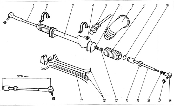
Figure 9.6. Steering gear
1 - left steering rod, non-adjustable; 2 - fastening clip; 3 - steering gear; 4 - input shaft of the transmission; 5 - steering column pivot shaft; 6 - threaded end of the toothed rack; 7 - steering column pivot shaft housing; 8 - steering gear casing; 9 - washer; 10 - inner ball joint; 11 - suspension beam; 12 - transmission cage bolts; 13 - inner joint safety nut; 14 - rubber casing socket; 15 - adjustable right steering rod; 16 - outer hinge safety nut; 17 - outer hinge nut; 18 - hinge.
3. With the power steering system installed, disconnect the fluid suction line 13 from the pump unit, see Figure 9.7. Drain the fluid into a prepared container.
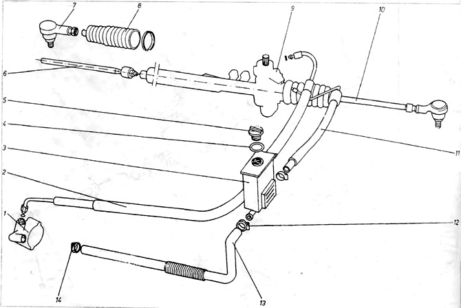
Figure 9.7. Power steering
1 - pump; 2 - pipeline under pressure; 3 - oil tank; 4 - gasket; 5 - oil tank cap; 6 - right steering rod; 7 - outer ball joint; 8 - steering gear casing; 9 - steering gear; 10 - left steering rod; 11 - return pipeline; 12, 14 - clamping belts; 13 - suction pipe.
4. Where available, disconnect the transmission movement bracket from the steering gear.
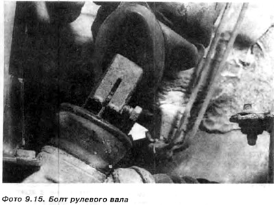
5. Lift and remove the cross-shaped joint housing 7, see Figure 9.6, and move it up the shaft to provide access to the clamping bolt. Loosen and remove the clamping bolt (Photo 9.15) connecting the transmission pinion to the steering column joint.
6. Loosen and remove both nuts securing the steering gear assembly and remove collars 2, see Figure 9.6. Note that the supporting bolts remain in the auxiliary frame. If necessary, these bolts can be removed by knocking them down with a metal punch.
7. In vehicles with power steering, it is necessary to disconnect the pressure 2 and return 11 pipes from the ends of the steering gear unit (figure 9.7).
8. To be able to remove the steering gear assembly, it may be necessary to disconnect the steering column and lift it up so that the cross-joint can be removed from the pinion shaft.
9. Remove the steering gear assembly through the hole in the left wheel arch casing.
10. In vehicles with power steering, use a jack to support the reinforcement frame, then unscrew and remove the left bolt of the reinforcement frame
11. Remove the steering gear assembly from the left side, pulling it out next to the slightly lowered reinforcement frame. The power steering fluid line must be plugged when removing the gear to prevent debris from getting inside.
12. Remove the steering rods from the steering gear as described in step 7.
13. Assembly is carried out in the reverse order of disassembly. All self-locking nuts must be replaced with new ones.
14. Set the wheels to drive straight and put on the steering column cross joint so that the steering wheel cross member is level with it.
15. All nuts and bolts must be tightened only after the car is installed on the ground. Check and, if necessary, adjust the toe-in of the front wheels.
16. In vehicles with power steering, remove the plugs from the fluid lines and from the air bleed hole in the tank cap. Connect the lines, making sure that no debris gets into the system. Add fluid to the system as described in point 10 and finally check for leaks.
Visitor comments