



Remove the flywheel and clutch drive disc.
If you also need to remove the clutch pressure plate, use a screwdriver to remove the locking ring of the release plate.
Remove 6 bolts in the pressure plate.
Remove the pressure plate together with the disc spring.
Blow the flywheel with compressed air or wipe it with a rag soaked in gasoline. Take this opportunity to check whether the centering pins are firmly fixed in the flywheel.
The old pressure plate can only be installed if the riveted connections are still sufficiently secure.
The surface on which the drive disk rests must be free of cracks or burnt spots. The deflection must not exceed 0.33 mm inward. To measure, place a metal ruler transversely on the pressure disk and measure at the inner edge using a feeler gauge.
Insert the disc spring into the pressure plate.
Lubricate new bolts with a preservative. The tightening torque should be 75 Nm.
Apply a small amount of grease to the bearing surface of the thrust disc and the surface with which the clutch pusher contacts.
Insert the separating disc so that its groove for the clutch pusher is directed towards the gearbox.
In a clutch assembly with a leading disc having a diameter of 190 mm, the ends of the locking ring should be directed towards the gearbox. If the disc diameter is larger and equals 200 mm, the ends should be directed towards the engine.
Lubricate the internal splines of the drive disk with a small amount of grease so that the disk slides well on the gearbox shaft.
Insert the clutch drive disc, the protruding splined part should be directed towards the gearbox.
Install the flywheel so that its centering pins fit into the corresponding holes or slots in the pressure plate. Otherwise, the "OT" marks on the flywheel and pressure plate will not match.
When tightening the flywheel bolts, the clutch drive disc must be centered. For this purpose, workshops use special tool 547.
Auxiliary method: without tightening the flywheel fastening, you can check the gap between the outer edge of the drive disk and the inner side of the flywheel. To do this, you will need a sliding gauge.
The gap should be the same size around the entire circumference. Otherwise, move the clutch master disk until it is exactly in the middle. Tighten the flywheel screws with a torque of 20 Nm.
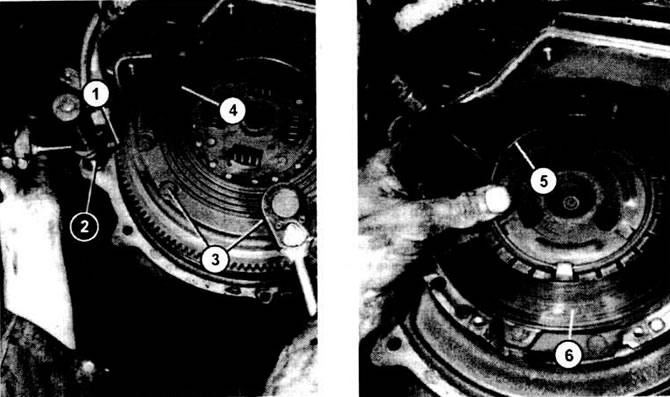
The illustrations show the dismantling of the clutch. Left: to unscrew the screws (3) of the flywheel (4), insert a screwdriver (2) into one of the holes and a second screwdriver (1) into the toothed ring and secure with this screwdriver. On the right, the retaining ring (5) of the pressure plate (6) is slightly raised.
(The original article is posted on the website: «www.VWManual.ru»)
Visitor comments