



Contents: Cold start with preheating ↓ Various options ↓ Electrical diagram used after August…↓ Electrical diagram used before July…↓ Starter and glow switch ↓
Due to the upward movement of the piston, the air in the cylinder is not only strongly compressed, but also significantly heated. The fuel injected into the hot air ignites.
But when the engine is cold, for example in winter, the temperature of the compressed air does not reach the ignition temperature of the fuel.
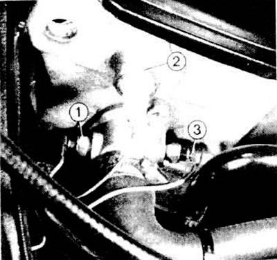
From the left front side (if you look in the direction of movement) the cylinder heads are located: 1 - temperature indicator sensor; 2 - oil pressure sensor; 3 - engine temperature sensor for pre-heating system
Cold start with preheating
To start a cold engine, you need to increase the air temperature in the cylinders.
The glow plug tubes in the swirl chambers of the cylinders serve this purpose. The glow tubes are heated by current from the battery. In this way, the air in the swirl chambers is additionally heated.
Various options
In the diesel Golf models of different years, there are two different electrical circuits for installing the pre-heater. Starter and glow switch (ignition in winter) has the following external features:
- Until July 1977, the starter switch lock had an additional position "Vorgluhen" ("Pre-glow"). The ignition key remained in this position until the pre-glow indicator lamp went out. Then the engine was started.
- After August 1977, this additional key position was no longer present. The updated starter and glow switch matched the ignition switch of carburettor models. The electrical circuit of the pre-glow system was also changed.
- After August 1980, further improvements were made to the rapid glow system (the wiring diagram is the same). The glow system differs from previous versions in that it has a different pre-glow relay and different glow plugs, which reach the required temperature much faster.
Electrical diagram used after August 1977.
On this wiring diagram pre-heating systems.
There are four glow plugs in the current line 19-22. They are not switched on one after another in sequence, as is done by some manufacturers; each individual glow plug receives full voltage (parallel connection). In line 19 on newer models, a 50 A blade fuse is connected. It is located in the black block near the rear bulkhead in the engine compartment.
Electric current flows from terminal 30 through the pre-glow relay contact. Inside the relay (J52 on the wiring diagram) there is an electronic circuit; the transistor designation indicates this. This circuit receives from the engine temperature sensor (current line 17) information about the current engine temperature. When the starter switch is in its first position, the electronic control extinguishes the pre-glow indicator lamp after a certain time. The time interval before the lamp goes out (that is, during the period when preliminary heating is carried out) is determined depending on the engine temperature. At an engine temperature of 0 degrees Celsius, the additional glow time is 25 seconds in a conventional glow system and 7 seconds in a fast glow system.
After the pre-glow indicator lamp goes out, the so-called additional glow period begins. It is 15 seconds in the normal system and 6-7 seconds in the fast glow system.
As soon as the starter switch is turned further, the starter starts the engine. The glow plugs also receive electric current during this period. If you turn on the starter by releasing the key, the glow process is also interrupted, regardless of whether the additional glow is finished or not. In order for the electronic circuit to "know" when it should finish the additional glow after the starter is turned off, a relay is connected to terminal 50 of the starter and glow switch.
Electrical diagram used before July 1977.
In the diesel model "Golf" of the first design series, pre-heating is carried out similarly. However, there is no additional automatic heating. For this reason, the pre-heating relay does not have a connection for terminal 50.
When the ignition key is held in the glow position, current is supplied to the glow plugs, since at the same time the switching contact of the pre-glow relay releases the flow of electric current. From the engine temperature sensor, the relay electronic circuit receives information about the temperature, which determines when the indicator lamp will be extinguished.
During the engine start process, the spark plugs continue to heat up further. Only after the starter is turned off are they left without electric current.
Starter and glow switch
The Golf models were equipped with two types of starter and glow plug switches (ignition switch).
Until July 1977, the switch had 4 switching positions: "Aus" ("Off"), "Fahren" ("On"), "Vorgluhen" ("Pre-heating"), "Anlassen" ("Start").
Subsequently, a switch was installed in which the "On" and "Pre-glow" positions were combined into one.
Visitor comments