
English Русский
Български
Беларускі
Український
Српски
Hrvatski
Română
Polski
Slovenský
Magyar
  |  Articles  |  Sitemap  |  Contacts  |    |
Car maintenance Ford Car maintenance Hyundai Car maintenance Chevrolet Car maintenance BMW Car maintenance Audi Car maintenance Opel Car maintenance AvtoVAZ
VWmanual.ru


Main   Passat   Golf   Polo   Touareg   Tiguan   Sharan   Transporter   Others  
Golf 1 (1974-1984, diesel) Golf 1 (1974-1984, petrol) Golf 2 (1984-1993, petrol) Golf 2 (1984-1993) Golf 3 (1991-1997) Golf 4 (1997-2004) Golf 5 (2003-2008)

Instrument cluster (VW Golf 1)

  • Main
  • Golf
  • Golf 1
  • Electrical equipment
  • Lighting and appliances
  • Instrument cluster
            0


Contents: Replacement ↓ Voltage stabilizer - replacement ↓ Printed circuit board - replacement ↓ Speedometer replacement ↓ Replacing the tachometer and clock ↓ Temperature indicator ↓

Replacement


1. Before starting work on the instrument panel, be sure to disconnect the ground wire from the battery.

2. Remove the steering wheel (see chapter "Steering").

3. Remove the handles from the heater control levers.

4. Remove the heater control unit trim.

5. Press the decorative window plug to install the radio (with the radio installed, you must remove its front panel and control knobs - see chapter "Additional equipment").

6. Remove the screws securing the instrument panel frame and pull the frame into the passenger compartment (figure P:7).

Remove the indicator lights and switches from the instrument panel frame by releasing the clips and pushing each element towards the interior

8. Remove the instrument panel frame.

9. Remove the two screws securing the instrument panel (instrument cluster - Figure P:8).
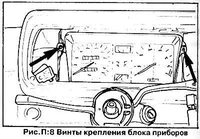
9. Remove the two screws securing the instrument panel (instrument cluster - Figure P:8).


10. Disconnect the speedometer cable from the back of the dashboard by squeezing the two plastic tabs together.


11. Disconnect the central connector and remove the instrument panel.

The instrument panel is installed in the reverse order of removal. Check the operation of all switches, signal lamps and instruments.

Voltage stabilizer - replacement


On cars manufactured before August 1975, the voltage stabilizer was built into the fuel level and temperature gauges. Since August 1975, the voltage stabilizer for the fuel level and temperature gauges has been installed as a separate device.

1. Remove the instrument panel as described previously.

2. Unscrew the stabilizer mounting screw, disconnect the wires and remove the voltage stabilizer (2, figure P:9).
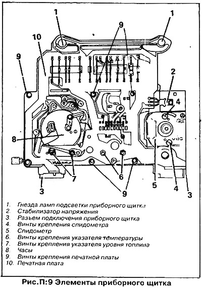
2. Unscrew the stabilizer mounting screw, disconnect the wires and remove the voltage stabilizer…


3. Installation of the voltage stabilizer is carried out in the reverse order.

Printed circuit board - replacement


1. Remove the instrument panel and voltage stabilizer as described earlier.

2. Carefully remove the lamp holders from the sockets on the shield and the printed circuit board (1, figure P:9).

3. Loosen the nuts and screws securing the printed circuit board and carefully remove the printed circuit board from the instrument panel (9, figure P:9).

4. Installation of the printed circuit board is carried out in reverse order.


Speedometer replacement


Remove the instrument panel as described above.

1. Remove the printed circuit board and voltage regulator.

2. Remove the bolts of the carrier plate and instrument casing (if available) and remove the carrier plate and casing.

3. Loosen the speedometer mounting screws and remove it (4, figure P:9).

4. The speedometer is installed in the reverse order.

Replacing the tachometer and clock


Tachometer removal and installation procedure (if available) and the clock is similar to that described above for the speedometer.

Temperature indicator


If the indicator shows "HOT" ("high temperature" - the needle is in the red zone), make sure that there is no actual engine overheating due to a faulty cooling system (see chapter "Cooling system").

If the indicator always shows "COLD" ("low temperature"), this is due to a defect in the sensor, pointer or wiring.

Check the circuit using a test lamp with wires. To avoid damaging the temperature gauge, connect a 12 V, 6 W test lamp between the temperature sensor wire and the ground when checking. The sensor is located in the housing at the end of the cylinder head on the flywheel side.

Disconnect the wire from the sensor and connect a test lamp between the wire and the ground. If the pointer moves to the "NOT" zone, replace the defective sensor.

If the arrow remains in the "COLD" position, the device itself or its wiring is faulty. Removing the fuel level and temperature indicators is done in the same way as the speedometer.

This article is available at russian, bulgarian, belarusian, ukrainian, serbian, croatian, romanian, polish, slovak, hungarian
The text has been checked: Tarasov Ivan

Share information:

Previous articles
Fuses, relays and turn signal switch
Replacing the lights
Replacing lamps
Tools and equipment
General information about electrical equipment
Next articles
Ignition Switch/Steering Column Lock
Switches and cigarette lighter
Windscreen wipers and washers
Sound signal
Gear shift/fuel consumption indicator
Possible electrical equipment faults


Similar articles from other manuals for VW cars:
Removal and installation the instrument cluster Passat B2 (1981-1988)
Instrument cluster, oil pressure control (since 10.1995) Polo 3 (1995-2003)
Black and white display in the instrument cluster Touareg 1 (2002-2006)
Instrument cluster Tiguan 1 (2007-2015)
Instrument cluster — design description Transporter T4 (1990-2003)
Instrument cluster Caddy 3 (2003-2010)
Link to this page in different formats


Visitor comments


No comments yet


How much will 25 + 42 =


Golf 5 
  • General information
  • User manual
  • Maintenance
  • Troubleshooting
  • Power unit
  • Engine repair
  • Cooling and ventilation system
  • Fuel system
  • Ignition system
  • Transmission
  • Clutch
  • Mechanical gearbox
  • Automatic gearbox
  • Chassis
  • Brake system
  • Car suspension
  • Steering
  • Body
  • Interior (internal elements)
  • Exterior (external elements)
  • Doors and covers
  • Electrical equipment
  • Power devices
  • Washers and wipers
  • Lighting and appliances
  • Electrical circuits
Golf 4 
  • General information
  • User manual
  • Weekly checks
  • Maintenance
  • Power unit
  • Petrol engines
  • Diesel engines
  • Cooling system
  • Fuel system (petrol)
  • Control system (petrol)
  • Fuel system (diesel)
  • Exhaust system
  • Transmission
  • Clutch
  • Car gearbox
  • Drive shafts
  • Chassis
  • Car suspension
  • Steering
  • Wheels and tires
  • Brake system
  • Body
  • Exterior (external elements)
  • Interior (internal elements)
  • Ventilation and heating
  • Car doors and sunroof
  • Washers and glass cleaners
  • Electrical equipment
  • Power devices
  • Lighting and appliances
  • Electrical circuits
Golf 3 
  • Petrol engine
  • Engine repair
  • Lubrication system
  • Cooling system
  • Ignition system
  • Diesel engine
  • Engine repair
  • Diesel injection system
  • Pre-glow system
  • Transmission
  • Clutch
  • Gearbox and drive shafts
  • Chassis
  • Steering
  • Wheels and suspension
  • Brake system
  • Electrical equipment
  • Lighting and appliances
  • Electrical circuits
Golf 2 
  • General information
  • Introduction to guide
  • User manual
  • Petrol engines 1.3 l
  • Engine repair
  • Lubrication system
  • Cooling system
  • Carburetors
  • Supply system
  • Ignition system
  • Petrol engines 1.6/1.8 l
  • Engine repair
  • Supply system
  • Ignition system
  • Diesel engines
  • Engine repair
  • Lubrication system
  • Cooling system
  • Power and exhaust system
  • Transmission
  • Clutch
  • 4-speed gearbox 084
  • 5-speed gearbox 085
  • 4-speed gearbox 020/4R
  • 5-speed gearbox 020/4T
  • Automatic gearbox
  • Drive shafts
  • Chassis
  • Steering
  • Car suspension
  • Brake system
  • Body
  • Body elements
  • Doors, locks and windows
  • Electrical equipment
  • Equipment and devices
  • Power devices
Golf 2 (petrol) 
  • General information
  • Characteristics
  • Car care
  • Maintenance
  • Power unit
  • Engine repair
  • Engine 1.05/1.30
  • Engine 1.60/1.80
  • Cooling and lubrication system
  • Power and exhaust system
  • Transmission
  • Clutch
  • Car gearbox
  • Drive shafts
  • Chassis
  • Brake system
  • Steering
  • Suspension
  • Body
  • Body and equipment
  • Electrical equipment
  • Lighting and appliances
  • Electrical circuits
Golf 1 (petrol) 
  • General information
  • Characteristics
  • User manual
  • Maintenance
  • Power unit
  • Engine adjustment
  • Engine 1.1/1.3
  • Engine 1.5/1.6/1.8
  • Engine electrical equipment
  • Cooling system
  • Fuel system
  • Transmission
  • Clutch and manual gearbox
  • Automatic gearbox
  • Chassis
  • Steering
  • Front suspension
  • Rear suspension
  • Brake system
  • Electrical equipment
  • Lighting and appliances
  • Electrical circuits
  • Body
  • Body and equipment
  • Optional equipment
Golf 1 (diesel) 
  • General information
  • Specifications
  • Maintenance
  • Power unit
  • Engine repair
  • Exhaust and turbocharger
  • Cooling system
  • Fuel system
  • Fuel injection system
  • Transmission
  • Clutch and drive shafts
  • Car gearbox
  • Chassis
  • Suspension and wheels
  • Steering
  • Brake system
  • Wheels and tires
  • Body
  • Heating and ventilation
  • Exterior (external elements)
  • Interior (internal elements)
  • Doors and windows
  • Electrical equipment
  • Equipment and devices
  • Lighting system
  • Power devices
  • Electrical circuits
VWmanual.ru © 2016-2026 | Mobile version | News and articles | Sitemap: EN BG BY UA RS HR RO PL SK HU | Write message | Site search
Passat B2 • Passat B3 • Passat B4 • Passat B5 • Passat B6 • Golf 1, diesel • Golf 1, petrol • Golf 2, petrol • Golf 2 • Golf 3 • Golf 4 • Golf 5 • Polo 3 • Polo 4 • Touareg 1 • Tiguan 1 • Sharan 1 • Transporter T3 • Transporter T4 • LT 28 • LT 2D • Beetle • Caddy 3 •
Our website uses cookies to ensure functionality and convenience.