
Removing
On early models (until July 1974) the steering column was fixed rigidly. Since August 1974, the mount has been changed - the lower part of the steering column is attached to the pedal bracket with a rubber mounting ring and a flat spring. With a strong frontal impact, the spring is squeezed out of its place, and the steering column goes to the side.
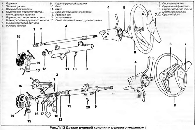
The steering column is removed as an assembly with the steering wheel and shift paddles mounted on the column (pic. L:12).
1. Disconnect the wire "masses" from the battery.
2. Turn out screws and remove a casing from understeering switches.
3. Disconnect the wire connectors of the switches and the ignition switch (see chapter "electrical equipment").
4. On early models, disconnect from the brake pedal the master cylinder pusher or servo rod, which are attached to the pedal with a pin and a spring ring. Also, unhook the cable from the clutch pedal and disconnect it from the guide on the pedal bracket.
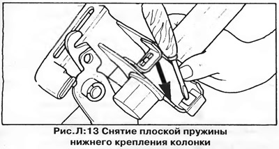
On vehicles with a resilient steering column, press the spring clip on the lower edge of the pedal bracket and remove the flat spring (pic. L:13).
5. Turn out a tightening bolt fixing the top hinge of a steering shaft to a steering column shaft.
6. Turn away nuts of fastening of the bottom arm of a steering column and screws of fastening of the top arm (pic. L:12). If the top bracket is secured with shear bolts, you can try to loosen them by hitting the barb tangentially into the edge of the head. If this does not help, the bolts need to be drilled out.
7. Remove a steering column from the car.
Installation
Installing the column is carried out in the reverse order of removal. Pay attention to the following:
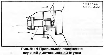
- A) When installing the top spacer, remember that the distance between the top edge of the spacer and the end of the shaft must be 41.5mm ("A", pic. L:14), while providing a gap of 2-4 mm between the lower edge of the steering wheel hub and the housing of the steering column switches ("b", pic. L:14).
- b) When installing a new mounting ring, heat it in hot water and pull it over the steering column housing so that the distance from the edge is 31 mm.
Before attaching the steering shaft, set the steering wheel and steering mechanism to the position corresponding to the direct direction of the wheels. Align the clamp bolt groove on the steering column shaft with the slot in the upper steering shaft pivot (rice. L:11).
Tighten all bolts and nuts to the torque specified in section "Technical data".
Tighten the top bracket shear bolts until the heads are sheared.
Adjust the clutch cable if necessary (see chapter "Clutch and manual transmission").
Visitor comments