
Caution: Removal and installation of individual components of the steering column switch must be carried out in the prescribed sequence. After installing the new steering column electronics control unit -J527-, it must be programmed (encode). If the steering column switch does not function correctly, the coding of the steering column electronics control unit -J527- must be checked.
Fault recognition and error indication
The steering column electronics control unit -J527- is equipped with a self-diagnosis system that facilitates troubleshooting. For troubleshooting, use the tester -VAS 5051A- in the "guided troubleshooting".
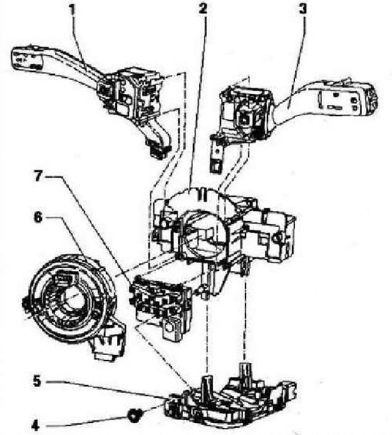
- 1 - Turn signal switch, follow the removal and installation sequence. "Turn signal switch" consisting of elements of turn signal switch -E2-, manual headlight switch for dipped beam and main beam headlamp -E4- and depending on equipment (Cruise control) from the cruise control switch -E45-. The picture shows "turn signal switch" Without cruise control switch -E45-
- 2 - Bracket for steering column switches
- 3 - Wiper switch -E-
- 4 - Fixing bolt
- 5 - Steering column electronics control unit -J527-
- 6 - Airbag coil spring and return ring with slip ring -F138-
- 7 - Steering angle sender -G65-
The sequence of removal and installation of structural elements of the steering column switch
When removing the steering column switch assembly with the bracket, it is disassembled, and the steering column lock housing is also removed. New shear screws are required to install the steering column lock housing. Even if only one stalk element needs to be removed or replaced, the following procedure must always be followed. Disconnect battery. Remove steering wheel. Remove steering column trim. Remove the components of the steering column switch in the following sequence.
- Steering column electronics control unit -J527-
- Airbag coil spring and return ring with slip ring -F138-
- Steering angle sender -G85-
- Turn signal switch -E2-
- Wiper switch -E-
- stalk bracket
Installation is carried out in the reverse order.
Removing and installing steering column electronics control unit -J527-
Caution: The removal and installation of the individual components of the steering column switch must follow the prescribed sequence. After installing a new control unit, it must be coded. If the steering column switch does not function properly, check the coding of the control unit.
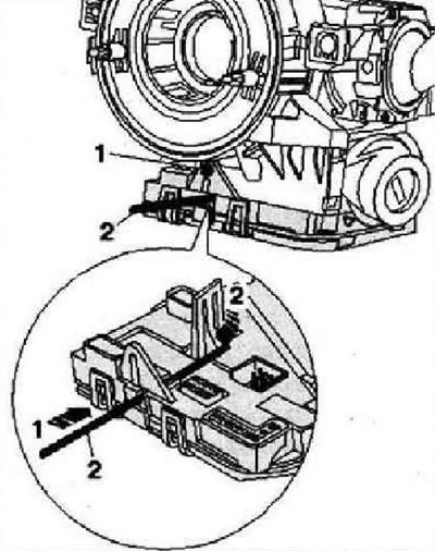
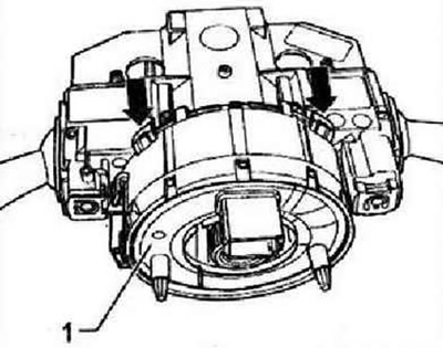
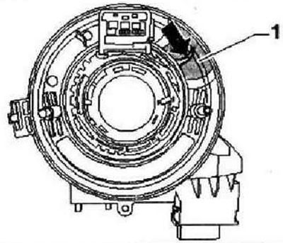
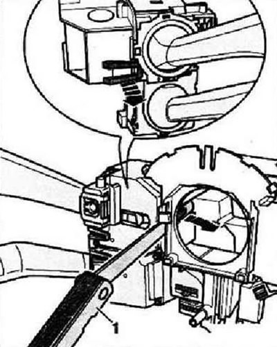
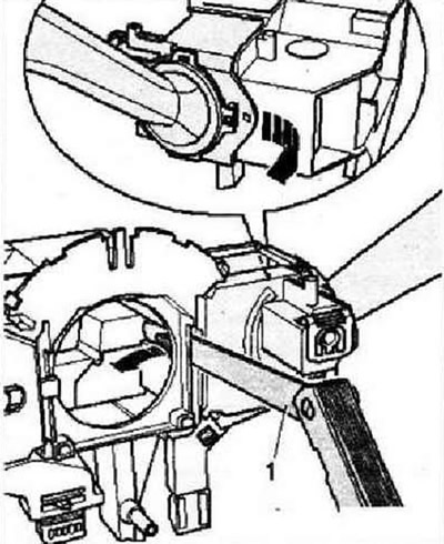
Remove screw -1-. On steering column control unit -J527-, insert appropriate wire -2- approx. 45 mm into hole -arrow 1- and release front locking latch -arrow 2-.
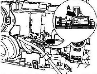
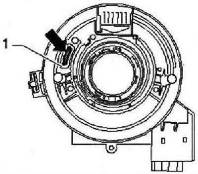
Use a suitable screwdriver to press the tab on the rear lock -arrow A- towards the steering wheel towards the rear to release the lock. Carefully pull steering column electronics control unit -J527- down from steering column switch.
Note: When tightening, make sure that the steering column electronics control unit -J527- comes out straight and without distortion downwards.
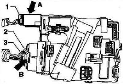
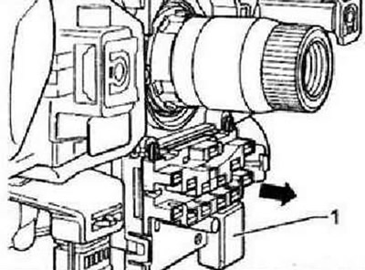
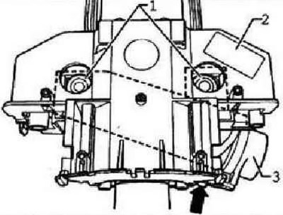
Release -arrow A- connector -1- and disconnect it from steering column electronics control unit -J527-. Remove retainer -3- from socket -2-. Release -arrow B- connector -2- and disconnect it from steering column electronics control unit -J527-.
Installation is carried out in the reverse order.
Instructions: When connecting the connectors, make sure that the contacts are not bent and that the connector connects with a click.
Removing and installing airbag coil spring and return ring with slip ring -F133-
Instruction: When dismantling, the coil spring must not be twisted out of the neutral position, the wheels must be in "position for rectilinear movement".
Raise hinges -arrows- on coil spring -1- slightly and pull coil spring back from steering column and switch module.
Installation is carried out in the reverse order.
Instruction: When installing, the coil spring must be in the neutral position and the wheels must be turned in "rectilinear position".
The following shows the neutral position of the coil spring, which varies by manufacturer. Colored ledge (black rectangle) -arrow- must be in viewing window -1-.
The yellow colored tape -arrow- must be in the viewing window -1-.
Note: After installing a new steering wheel angle sender -G95-, carry out "basic setup".
Removing and installing steering wheel angle sender -G85-
Pull steering angle sender -G85- -1- back off steering column switch -arrow-.
Installation is carried out in the reverse order.
Removal and installation of the switch of indexes of turn
Instruction: "Turn signal switch" consisting of turn signal switch -E2-, dipped beam and light switch -E4- and, depending on equipment, (Cruise control) cruise control switch -E45-. For clarity, the illustration shows the removed steering column switch with cruise control switch -E45-.
Release retaining clips -arrows- with feeler gauge 1.0 mm -1- and remove "turn signal switch" back (to the back of the car).
Installation is carried out in the reverse order.
Instruction: "Turn signal switch" should lock into place with a distinctly audible click.
Removing and installing wiper switch -E-
Instruction: For clarity, the figure shows the removed steering column switch.
Unlock retaining clips -arrows- with feeler gauge 1.0 mm -1- and pull wiper switch -E- back (to the back of the car).
Installation is carried out in the reverse order.
Instruction: Wiper switch -E- must engage with an audible click.
Removing and installing the steering column switch bracket
Instruction: To remove the steering column switch bracket -2-, it is necessary to drill out the shear screws of the steering column lock housing. New shear screws -1- are required for subsequent installation. Before drilling the shear screws, it is necessary to check that all components attached to the bracket have been previously removed. Drilling can introduce chips into neighboring components, which can cause malfunctions and/or malfunction of the components! Therefore, when removing the structural elements of the steering column switch, the prescribed sequence must be observed.
Disconnect battery. Remove all elements fixed to the bracket in the prescribed sequence. After all structural elements fixed on the bracket are removed, the bracket itself can be removed. Drill out fixing screws -1- for steering column lock housing -3-.
Instruction: M8 screws -1-, thread hole diameter 6.8 mm.
Pull steering column lock housing and steering column switch bracket -2- back out of steering column. Remove the steering column lock housing from the steering column switch bracket.
Installation
Insert the steering column lock housing into the steering column switch bracket. Push bracket -2- as far as possible onto steering column. Plug in connector -arrow- at pickup coil -3-. Screw the steering column lock housing with new shear bolts -1- to the steering column. Tighten new shear screws -1- until the heads are sheared off. Install all structural elements of the steering column switch, respectively, in reverse order.
Visitor comments