



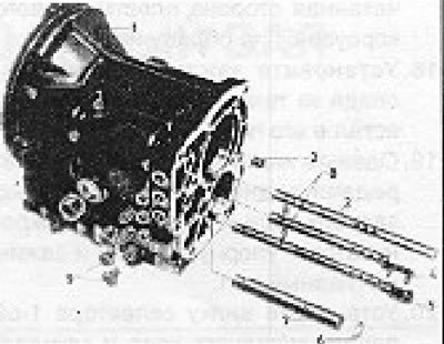
Figure 6.46. Selector components: 1 - Body; 2 - Ledge; 3 - 1st gear/reverse selector shaft; 4 - 2/3 gear selector shaft; 5 - 4/5 gear selector shaft; 6 - Spring clamp; 7 - Reverse sliding gear shaft; 8 - Intermediate plungers; 9 - Retaining plugs, springs and balls.
1. Place the main shaft into the gearbox housing.
2. Install the main shaft rear bearing with its sealed side facing inward.
3. Loosely install the bearing locking plate.
4. If you do not have a press, it is recommended to install the main shaft in its final position through its bearing using a piece of metal tubing and screwing a bolt into a tapped hole in the end of the shaft so that it applies pressure to the thrust washer located on the piece of tubing.
5. Insert the intermediate plungers of the selector shaft into their holes. Insert the selector shafts and set them to neutral position.
6. Install the springs and balls and partially tighten the retaining plugs.
7. Place the fork on the 2/3 speed selector shaft and insert and tap the roller pin. This will require partially removing the 1st/Reverse shaft to access the roller pin hole.
8. Place the 4/5 speed fork onto the selector shaft and install the locking roller pin. To do this, engage 4th gear by moving the synchronizer sleeve.
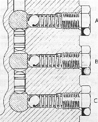
Figure 6.47. Sectional view of retaining components: A - 1st gear/reverse; B - 2/3 gear; C - 4/5 gear.
9. Insert the rear countershaft bearing into the housing. Before doing this, the loosely mounted main shaft bearing mounting plate must be removed. Make sure the sealed side of the plastic bearing housing faces inward.
10. Install the bearing mounting plates, tighten the screws to the required degree and tap the screws in place.
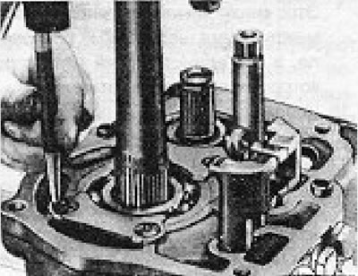
Figure 6.48. Tapping the bearing mounting plate screws.
11. Install the thrust washer and spring clip onto the rear end of the main shaft.
12. Install the needle bearing, 1st gear gear with synchronizer ring and mounting spring clip.
13. Lower the input shaft into the gearbox housing, making sure that its needle bearing and synchronizer ring are in place (the keys are aligned), place it on the main shaft and insert the bearing into the housing.
14. Lower the counter gear with its sleeve into the gearbox casing.
15. Pass the counter shaft through the counter gear assembly and at the same time fit the 1st/reverse synchronizer onto the main shaft. This synchronizer is located between the two countershaft gears, and this is the only method by which it can be installed.
16. Using a plastic-faced hammer, tap the countershaft and 1st/reverse synchronizer completely into place. Install the shaft spring clamp to secure the synchronizer hub.
17. Install the front countershaft bearing, applying force only to the inner race of the bearing and ensuring that the sealed side of the plastic housing faces inward.
18. Install the bearing clamp, making sure that:. so that it fits completely into its groove.
19. Install the reverse gear needle bearing, reverse gear and its synchronizer ring, thrust washer and clamp onto the main shaft.
20. Install the 1st/reverse selector fork and secure it with the roller pin.
21. Install the speedometer drive gear onto the rear end of the main shaft and secure it in place with the spring clip.
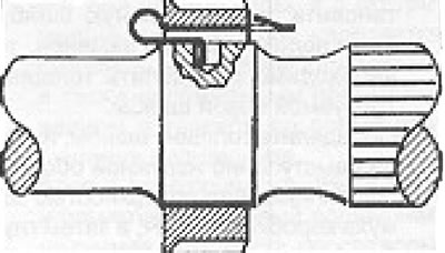
Figure 6.49. Position of the speedometer drive gear locking clamp.
The article is posted on this website (www.VWMANUAL.ru)
22. Install the oil pan using a new gasket. The magnet should be positioned towards the rear of the gearbox.
23. If removed, install the reverse gear sliding shaft in place, then put on the gear with thrust washers.
24. If you have not replaced the input shaft bearing, the original washer can be installed between the bearing and the clutch housing. If the bearing has been replaced, it is necessary to determine the thickness of the new washer required.
25. Determine the thickness of the washer by measuring the protrusion of the outer bearing race above the surface of the gearbox housing, and then the depth of the opening in the clutch housing. Use a measuring tool for this. Add 0.1mm to the opening depth to compensate for the thickness of the new shim. Subtract one measurement from the other to get the required thickness of the new washer. Washers are available in four sizes.
26. Using a new gasket, install the clutch cover bolts and tighten them to the specified torque. Apply a small amount of hardening putty to the bolt threads to prevent oil leakage.
27. Install the bearing and clutch release lever as described in Chapter 5.
28. Once the new gasket is installed, prepare the extension to fit into the transmission housing. Here it is necessary to follow a certain sequence of actions. First, advance the gearshift mechanism until it is in the engaged 2nd gear position. Do this by pulling the inner extension gear shift lever slightly outward, and then turning the end of it that has the ball on it towards the housing.
29. Install the extension in the correct position, ensuring that the selector finger is on the 4/5 speed selector shaft. Now turn the extension housing counterclockwise and align the pin with the 2/3 speed selector rod.
30. Once the extension housing is fully installed, check that all gears are engaged.
31. Tighten the expansion joint mounting bolts to the required torque.
Visitor comments