



2. Using a piece of metal of suitable thickness, check that measurement (a) matches that shown in Figure 6.31. If it does not,. release the pin through bolt and slide the pin up or down as needed.
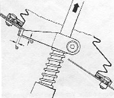
Figure 6.31. Adjusting the selector finger (Section 9): a = 2.0 mm; b = 3.0 mm.
3. Working under the vehicle, loosen the through bolt in the gear selector link clamp and adjust the position of the lever and link to provide clearance (b) between the end of the pin and the lock plate as shown in Figure 6.31.
4. When finished, press the selector lever to the right and tighten the through bolt of the clamp.

Figure 6.32. Gear selector linkage through bolt (Section 9).
5. Engage third gear by pulling the selector lever up approximately 10.0 mm and then pushing it back.
6. Release the through bolt of the tie rod clamp a second time, and press the selector lever to the left until it stops. Retighten the through bolt.
7. With the selector lever returned to the neutral position, push the lever to the left and measure the clearance (c) between the corner of the pin and the edge of the lock plate as shown in Figure 6.33. If adjustment is required, loosen the pin through bolt and rotate the pin, but do not change the pin installation height. When finished, tighten the through bolt.
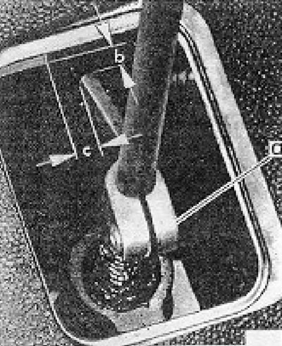
Figure 6.33. Adjusting the pin at the base of the gear shift lever (Section 9): a - through bolt; b = 3.0 mm; c = 3.0 mm.
8. After all adjustment operations are completed, engage each gear in turn. It should be impossible to move the gearshift lever directly from first gear to reverse gear. This is ensured by a correctly adjusted position of the finger, which rests against the locking plate.
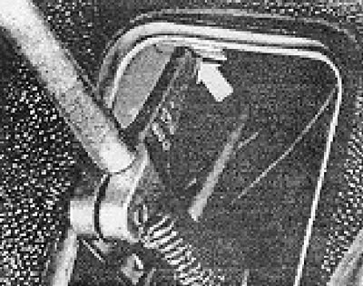
Figure 6.34. Remove the intermediate pin against the lock plate (Section 9).
Visitor comments