English Русский
Български
Беларускі
Український
Српски
Hrvatski
Română
Polski
Slovenský
Magyar
  |  Articles  |  Sitemap  |  Contacts  |    |
Car maintenance Ford Car maintenance Hyundai Car maintenance Chevrolet Car maintenance BMW Car maintenance Audi Car maintenance Opel Car maintenance AvtoVAZ
VWmanual.ru


Main   Passat   Golf   Polo   Touareg   Tiguan   Sharan   Transporter   Others  
LT 28 (1975-1991) LT 2D (1996-2003) Beetle (1960-1986) Caddy 3 (2003-2010)

Main shaft (4 speeds) — disassembly and assembly (VW Lt 28)

  • Main
  • Volkswagen
  • LT 28
  • Transmission
  • Car gearbox
  • Main shaft (4 speeds) — disassembly and assembly
            0


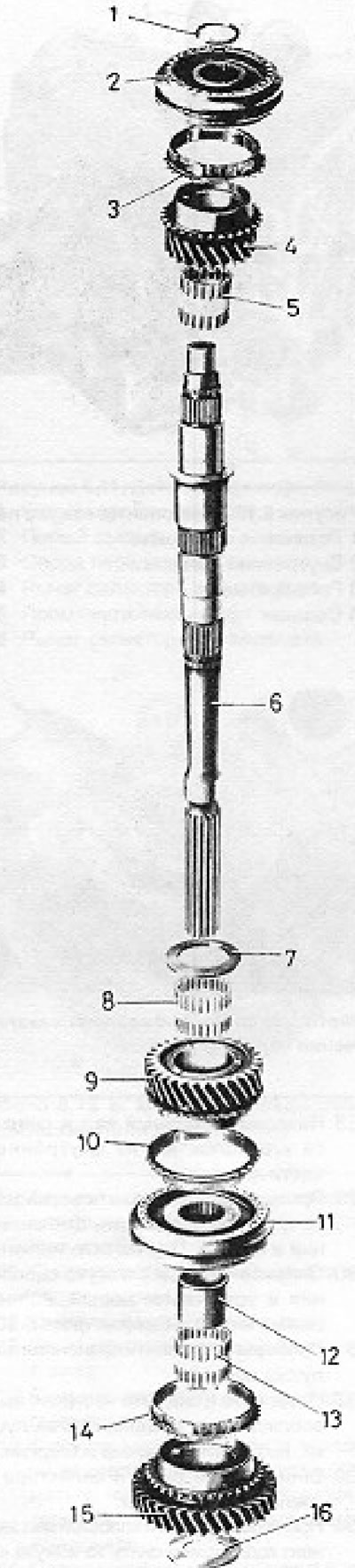
Figure 6.15. Main shaft components (Section 6): 1 - Spring clamp; 2 - 3/4 speed synchronizer; 3 -…

Figure 6.15. Main shaft components (Section 6): 1 - Spring clamp; 2 - 3/4 speed synchronizer; 3 - Synchronizer ring; 4 - 3rd gear pinion; 5 - Needle bearing; 6 - Main shaft; 7 - Thrust washer; 8 - Needle bearing; 9 - 2nd gear pinion; 10 - Synchronizer ring; 11 - 1/2 speed synchronizer; 12 - Bushing; 13 - Needle bearing; 14 - Synchronizer ring; 15 - 1st gear pinion; 16 - Thrust washer.


1. From the front end of the main shaft, remove the spring clip from the groove in the shaft, and then remove the 3/4 synchronizer and 3rd gear. They can be simply removed from the shaft without any problems.

2. Remove the 3rd gear needle bearing from the main shaft.

3. From the rear end of the main shaft, remove the 1st gear thrust washer, 1st gear, 1/2 gear synchronizer and 2nd gear. Do this either by supporting the rear face of the 2nd gear and pulling the components off the shaft, or by using a suitable puller and placing it behind the gears. Be careful not to damage the gear teeth.

4. Remove the needle bearings for the 1st and 2nd gears, as well as the 2nd gear thrust washer.

5. With the main shaft completely disassembled, check for chipped or worn gears, loose or rattling bearings, and faulty synchronizers as described below.


6. The need for partial or complete replacement of synchronizers is usually known in advance due to the presence of noise when shifting gears.

7. Press the synchronizer ring onto the gear cone and turn it. It should fit snugly on the cone, and the gap between the ring and the teeth should not exceed 2.5 mm. If the gap is larger, replace the ring.
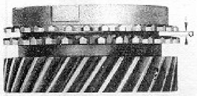
Figure 6.14. Synchronizer ring test diagram (Section 6). a = 2.5 mm

Figure 6.14. Synchronizer ring test diagram (Section 6). a = 2.5 mm


8. Check the remaining components for wear in the hub and cotter pins, as well as the condition of the teeth.

9. When assembling synchronizers, pay attention to the following points:
  • The 1st gear synchronizer ring has no notches on its outer edge, while the 2nd gear ring has three notches;
  • When aligning the synchronizer hub with the sleeve, try several positions until you find one that provides minimal wobble or "loose play." Also note that the 1/2-gear synchronizer has its sleeve groove located next to the second gear pinion when installed on the mainshaft;
  • The sliding keys should be positioned at an angle of 120° to each other, and the circular springs should be installed so that they rotate in opposite directions, with their curved ends aligned with the keys.
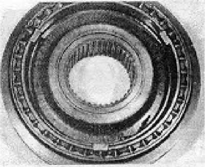
Photo 6.9a. 1/2-speed synchronizer.
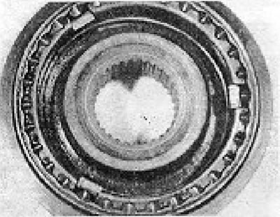
Photo 6.9a. 1/2-speed synchronizer.


Photo 6.9.b. 3/4 speed synchronizer.

Photo 6.9.b. 3/4 speed synchronizer.


(View the original on this portal VWManual.ru)

10. Continue assembly by installing the second gear thrust washer onto the rear end of the shaft. Make sure the non-grooved surface of the washer faces the 2nd gear side (see photo 6.10).
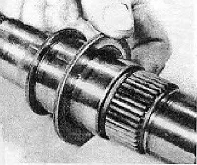
Photo 6.10. Installing the 2nd gear thrust washer on the main shaft.

Photo 6.10. Installing the 2nd gear thrust washer on the main shaft.


11. Lubricate and install the 2nd gear needle bearing (see photo 6.11).

Photo 6.11. Installing the 2nd gear needle bearing onto the main shaft.

Photo 6.11. Installing the 2nd gear needle bearing onto the main shaft.


12. Install the 2nd gear (see photo 6.12).
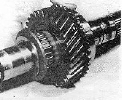
Photo 6.12. Installing the 2nd gear on the main shaft.

Photo 6.12. Installing the 2nd gear on the main shaft.


13. Install the 2nd gear synchronizer ring (see photo 6.13).
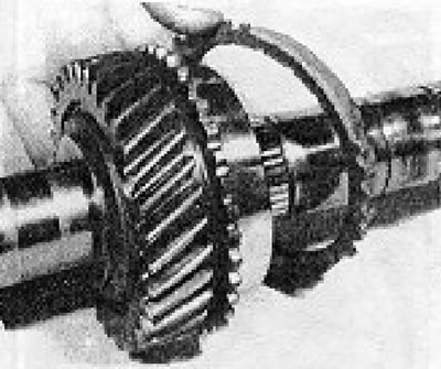
Photo 6.13. Installing the 2nd speed synchronizer ring on the main shaft.

Photo 6.13. Installing the 2nd speed synchronizer ring on the main shaft.


14. Install the 1/2 speed synchronizer, ensuring that the groove on the sleeve faces the 2nd gear gear (see photo 6.14).
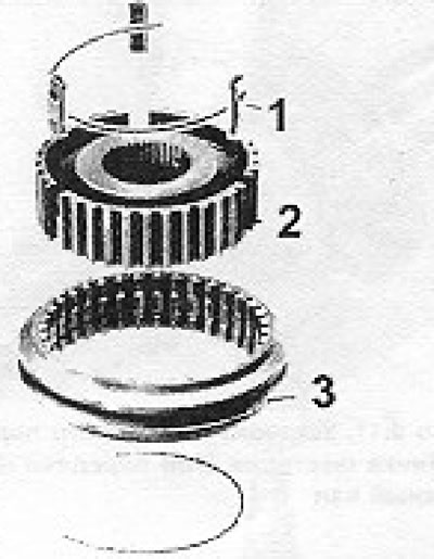
Figure 6.20. Components of the 1/2 speed synchronizer (Section 6): 1 - Locking key; 2 - Hub; 3 -…

Figure 6.20. Components of the 1/2 speed synchronizer (Section 6): 1 - Locking key; 2 - Hub; 3 - Sleeve.
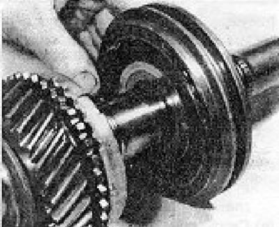

Photo 6.14. Installing the 1/2 speed synchronizer on the main shaft.

Photo 6.14. Installing the 1/2 speed synchronizer on the main shaft.


15. Install the 1st gear needle bearing together with its inner race, lubricating them thoroughly with oil (see photo 6.15).
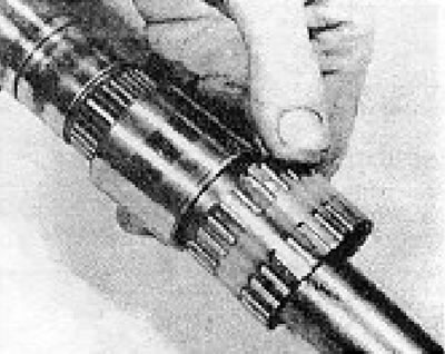
Photo 6.15. Installing the 1st gear needle roller bearing onto the main shaft.

Photo 6.15. Installing the 1st gear needle roller bearing onto the main shaft.


16. Install the 1st gear synchronizer ring (see photo 6.16).
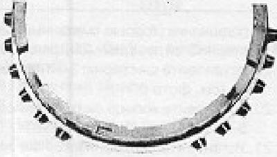
Figure 6.16. 1st gear synchronizer ring (Section 6).
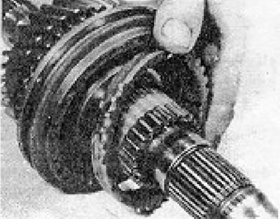
Figure 6.16. 1st gear synchronizer ring (Section 6).


Figure 6.17. 2nd gear synchronizer ring. Mark the notch (marked with an arrow) (Section 6).

Figure 6.17. 2nd gear synchronizer ring. Mark the notch (marked with an arrow) (Section 6).
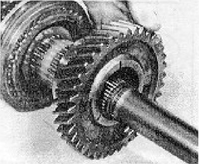

Photo 6.16. Installing the 1st speed synchronizer ring on the main shaft.

Photo 6.16. Installing the 1st speed synchronizer ring on the main shaft.


17. Install the 1st gear pinion and its thrust washer (see photos 6.17a and b).
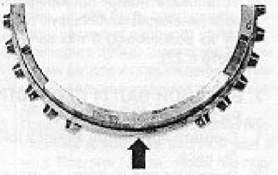
Photo 6.17a. Installing the 1st gear pinion on the main shaft.
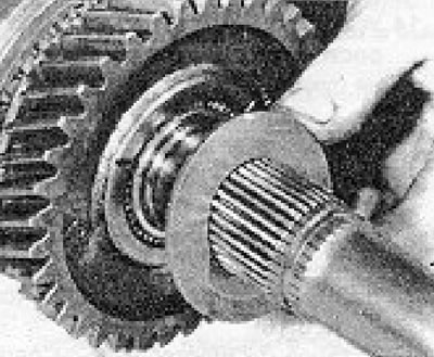
Photo 6.17a. Installing the 1st gear pinion on the main shaft.


Photo 6.17b. Installing the 1st gear thrust washer.

Photo 6.17b. Installing the 1st gear thrust washer.


18. Install a needle roller bearing on the front end of the main shaft (well lubricated) 3rd gear (see photo 6.18).
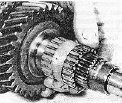
Photo 6.18. Installing the 3rd gear needle bearing on the main shaft.

Photo 6.18. Installing the 3rd gear needle bearing on the main shaft.


19. Install the 3rd gear (see photo 6.19).
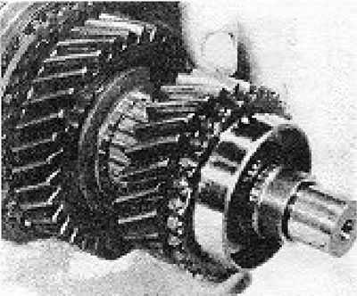
Photo 6.19. Installing the 3rd gear pinion on the main shaft.

Photo 6.19. Installing the 3rd gear pinion on the main shaft.


20. Install the 3rd speed synchronizer ring (see photo 6.20).
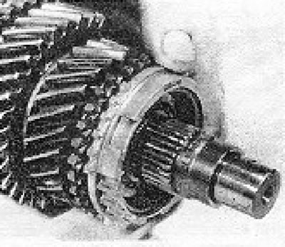
Photo 6.20. Installing the 3rd gear synchronizer ring.

Photo 6.20. Installing the 3rd gear synchronizer ring.


21. Install the 3/4 speed synchronizer so that its wider shoulder on the hub faces the 3rd gear gear (see photo 6.21).
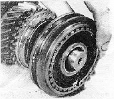
Photo 6.21. Installing the 3/4 speed synchronizer.

Photo 6.21. Installing the 3/4 speed synchronizer.


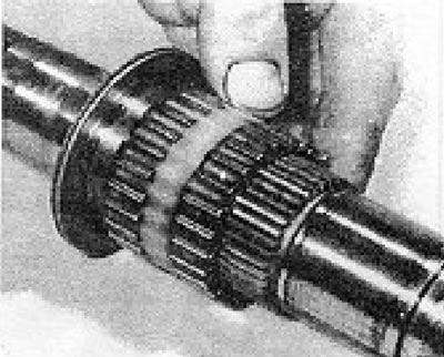
22. Install the new spring clip (having the greatest possible thickness) into the shaft groove (see photo 6.22).
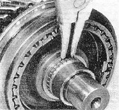
Photo 6.22. Installing the 3/4 speed synchronizer spring clip.
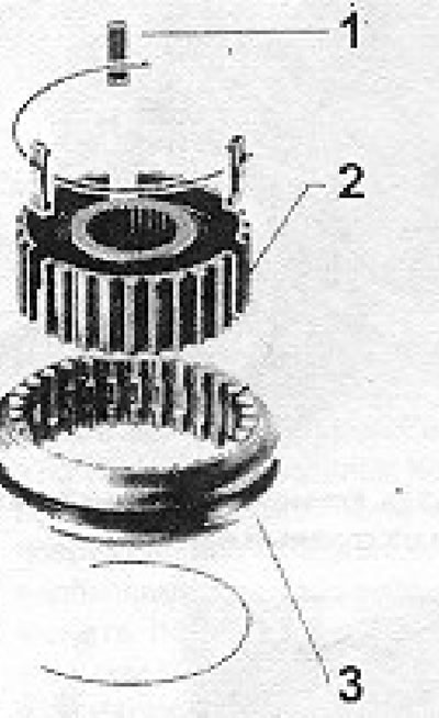
Photo 6.22. Installing the 3/4 speed synchronizer spring clip.


Figure 6.21. 3/4 Speed Synchronizer Components (Section 6): 1 - Locking key; 2 - Hub; 3 - Sleeve.

Figure 6.21. 3/4 Speed Synchronizer Components (Section 6): 1 - Locking key; 2 - Hub; 3 - Sleeve.

This article is available at russian, bulgarian, belarusian, ukrainian, serbian, croatian, romanian, polish, slovak, hungarian
The text has been checked: Kolesnikov Artem

Share information:

Previous articles
Gearbox (4 speeds) — disassembly into main components
Gearbox (4 speeds) — removal and installation
Gear shift mechanism (4 speeds) — removal, disassembly, assembly and installation
Gear shift mechanism (4 speeds) — adjustment
Description and maintenance of the gearbox
Gearbox specifications
Next articles
Input shaft (4 speeds) — disassembly and assembly
Gearbox (4 speeds) — assembly
Gear shift mechanism (5 speeds) — adjustment
Gear shift mechanism (5 speeds) — removal, disassembly, assembly and installation
Gearbox (5 speeds) — disassembly into main components
Main shaft (5 speeds) — disassembly and assembly


Similar articles from other manuals for VW cars:
Adjusting the bearings of the main gear drive shaft-pinion Passat B4 (1988-1996)
Auxiliary shaft seal Golf 1 (1974-1984, petrol)
Checking the levels of the main working fluids Polo 3 (1995-2003)
Replacing the generator drive shaft seal Touareg 1 (2002-2006)
Balance shaft drive chain Tiguan 1 (2007-2015)
Intermediate shaft — removal and installation Sharan 1 (1995-2000)
Speedometer shaft — removal and installation Transporter T4 (1990-2003)
Link to this page in different formats


Visitor comments


No comments yet


How much will 14 + 22 =


Caddy 3 
  • General information
  • User manual
  • Daily care
  • Maintenance
  • Petrol engines 1.4 l
  • Engine repair
  • Cooling and lubrication system
  • Power and exhaust system
  • Petrol engines 1.6 l
  • Engine repair
  • Cooling and lubrication system
  • Power and exhaust system
  • Diesel engines
  • Engine repair
  • Cooling and lubrication system
  • Power and exhaust system
  • Transmission
  • Mechanical gearbox 0AH
  • Mechanical gearbox 0A4
  • Drive shafts
  • Chassis
  • Car suspension
  • Steering
  • Brake system
  • Body and wiring diagrams
  • Interior and exterior
  • Electrical circuits
Beetle 
  • General information
  • Maintenance
  • Power unit
  • Engine repair
  • Cooling and lubrication system
  • Supply system
  • Exhaust system
  • Transmission
  • Clutch
  • Car gearbox
  • Chassis
  • Front suspension
  • Rear suspension
  • Steering
  • Brake system
  • Wheels and tires
  • Body
  • Exterior
  • Electrical equipment
  • Equipment and devices
  • Power devices
  • Electrical circuits
LT 2D 
  • General information
  • User manual
  • Maintenance
  • Power unit
  • Petrol engines 2.3 l
  • Diesel engines 2.5 l
  • Diesel engines 2.8 l
  • Injection system (diesel 2.8 l)
  • Transmission
  • Clutch
  • Manual gearbox
  • Differential
  • Chassis
  • Car suspension
  • Steering system
  • Brake system
  • Body
  • Body elements
  • Heating system
  • Electrical equipment
  • Equipment and devices
  • Electrical circuits
LT 28 
  • General information
  • Maintenance
  • Power unit
  • Petrol engines 2.0L
  • Petrol engines 2.4L
  • Diesel engines
  • Cooling and heating
  • Fuel and exhaust system
  • Ignition system
  • Transmission
  • Clutch
  • Car gearbox
  • Cardan shaft
  • Rear axle
  • Chassis
  • Brake system
  • Car suspension
  • Steering system
  • Body
  • Body elements
  • Doors, locks and windows
  • Electrical equipment
  • Power devices
  • Equipment and devices
  • Electrical circuits
VWmanual.ru © 2016-2026 | Mobile version | News and articles | Sitemap: EN BG BY UA RS HR RO PL SK HU | Write message | Site search
Passat B2 • Passat B3 • Passat B4 • Passat B5 • Passat B6 • Golf 1, diesel • Golf 1, petrol • Golf 2, petrol • Golf 2 • Golf 3 • Golf 4 • Golf 5 • Polo 3 • Polo 4 • Touareg 1 • Tiguan 1 • Sharan 1 • Transporter T3 • Transporter T4 • LT 28 • LT 2D • Beetle • Caddy 3 •
Our website uses cookies to ensure functionality and convenience.