



2. Tighten the end cover so that its edge is located 1.0 mm below the gearbox housing.
3. If you removed the reverse idler shaft, now install it in place using a brass hammer (see photo 8.3).
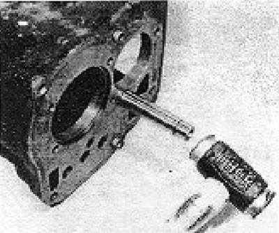
Photo 8.3. Installing the reverse idle shaft.
4. Install the reverse gear selector lever.
5. Lower the assembled main shaft into the gearbox housing (see photo 8.5).
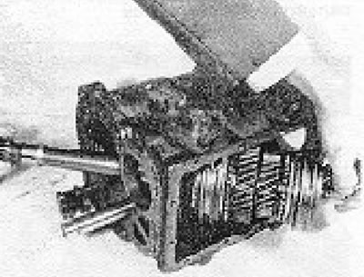
Photo 8.5. Installation of the main shaft structure.
6. Place the main shaft bearing onto the shaft and into the gearbox. Make sure the closed side of the bearing is facing inward (see photo 8.6).
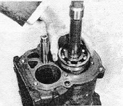
Photo 8.6. Installing the main shaft bearing.
7. Install the smaller of the two bearing mounting plates and insert its screws, but do not tighten them at this stage.
8. Now you will need to install the main shaft through the inner bearing race into its final position. Attach this by screwing a bolt into the end of the shaft and using a piece of tubing with a thrust washer in the same manner as described in removing the reverse idler shaft (see photo 8.8).
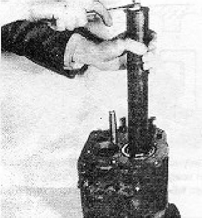
Photo 8.8. Passing the main shaft through the bearing. The bearing mounting plate must be installed first.
9. Using a thin magnet or long-nose pliers, insert the first intermediate plunger onto the reverse selector lever.
10. Insert the 1/2 gear selector lever and push it in far enough to allow the fork to be installed on it and secured. The 1/2 gear fork is the one with the most spread out levers (see photo 8.10 a and b).
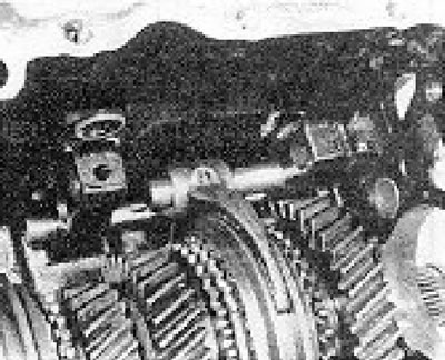
Photo 8.10a. Installing the 1/2-speed selector lever.
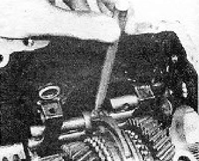
Photo 8.10b. Attaching the 1/2-speed selector fork to the lever.
11. Insert the second intermediate plunger.
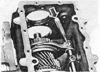
Figure 6.25. Attaching the 3/4 speed selector fork to its lever.
12. Install the 3/4 gear selector lever and its fork, and secure the fork in place. To make it easier to secure the fork, engage 3rd gear by sliding the synchronizer sleeve (see photo 8.12).
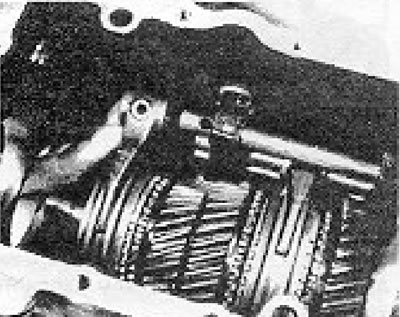
Photo 8.12. Installing the 3/4 speed selector lever and fork.
13. Install the input shaft as a whole, together with the needle roller bearing and synchronizer ring. Rotate the ring as necessary to align the grooves with the synchronizer sliding keys. Install the washer and spring clip (see section 7). (see photos 8.13a, b, c, and d).
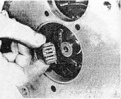
Photo 8.13a. Installing the input shaft needle bearing onto the main shaft.
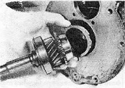
Photo 8.13b. Installing the input shaft.
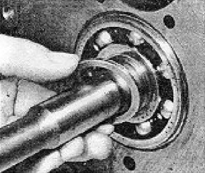
Photo 8.13c. Installing the input shaft washer.
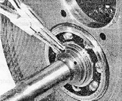
Photo 8.13d. Installing the input shaft spring clamp.
14. Guide the counter shaft into the gearbox housing and install the front and rear bearings using a piece of metal tubing to install them, positioning it on the central races. When installing bearings, make sure their numbers are visible from the outside of the gearbox casing (see photos 8.14a and b).
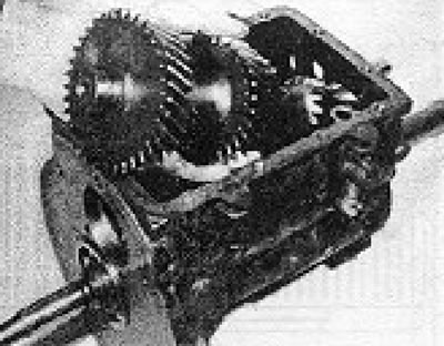
Photo 8.14a. Installation of the countershaft structure.
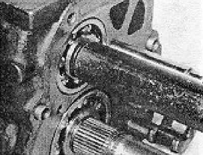
Photo 8.14b. Installing the countershaft bearings.
15. Install the bearing mounting plate and screws.
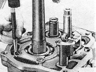
Figure 6.26. Tapping the bearing mounting plate screws.
16. Tighten the mounting plate screws to the required degree and nail them in place (see photos 6.16a and b).
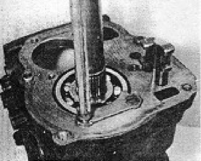
Photo 8.16a. Tightening the bearing mounting plate screws.
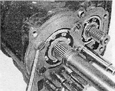
Photo 8.16b. Tapping the bearing mounting plate screws.
17. Insert the countershaft reverse gear, noting that the grooved teeth area should be located next to the clamp. If you have difficulty installing the gear, heat it in boiling water for a few minutes before installing it. Install the spring clip (see photos 8.17a and b).
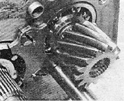
Photo 8.17a. Installing the reverse gear onto the countershaft.
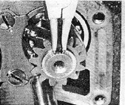
Photo 8.17b. Installing the reverse gear clamp on the counter shaft.
18. Heat the main shaft reverse gear in the same way and install it in place, paying attention to the fact that the grooves on the teeth should be facing the spring clamp when installed. Now you need to choose the right washer (of six different sizes), to ensure clearance between the gear and the washer after installing the spring clip. This selection is also carried out by trial and error. Then install the spring clip (see photo 8.18a, b and c).
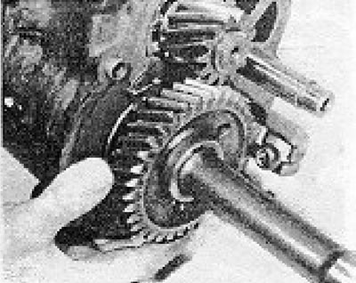
Photo 8.18a. Installing the reverse gear on the main shaft.
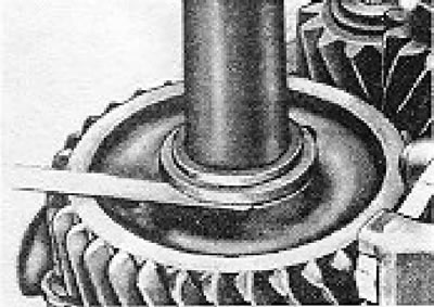
Figure 6.27. Measuring the clearance between the reverse gear on the main shaft and the washer.
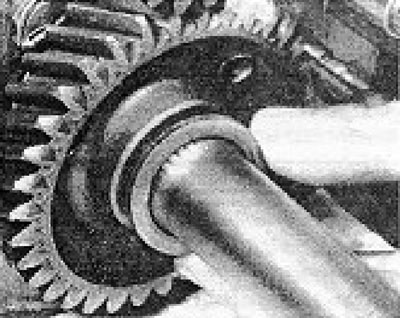
Photo 8.18b. Installing the reverse gear washer.
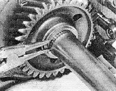
Photo 8.13c. Installing the reverse gear clamp.
19. If you removed the transmission link support, now install it and adjust it to the dimensions shown in Figure 6.28. When finished, tighten the lock nut. You will most likely need to use a socket wrench to do this, cut down for easier access (see photos 8.19a and b).
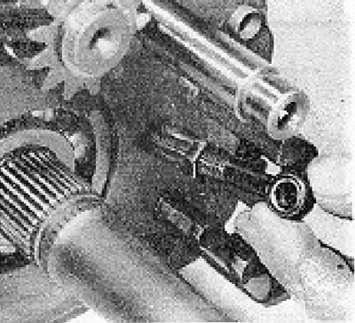
Photo 3.19a. Installing the transmission lever support.
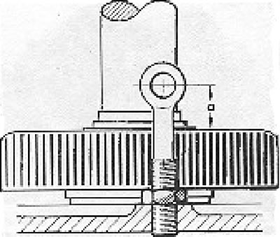
Figure 6.28. Adjustment diagram when installing the transmission lever. a = 15.7 to 16.5 mm.
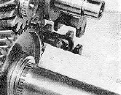
Photo 8.19b. Measuring the protrusion of the transmission lever support.
[The article is posted on this website www.VWManual.ru]
20. Install the transmission lever and gear (see photo 8.20).
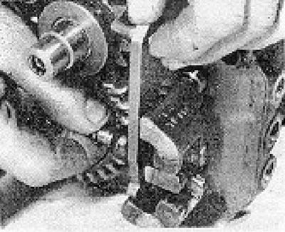
Photo 8.20. Installing the transmission lever and pin.
21. Secure the transmission lever pin with a clamp (see photo 8.21).
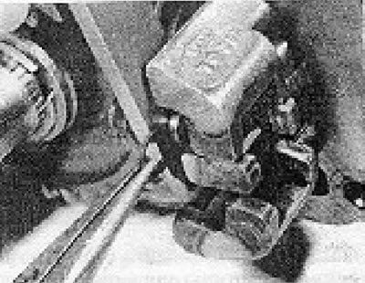
Photo 8.21. Securing the transmission lever pin with a clamp.
22. Install the retaining balls, coil springs and their mounting plugs (see photos 8.22a and b).
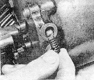
Photo 8.22a. Installing the retaining ball and spring.
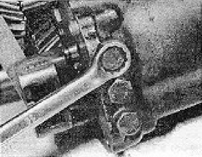
Photo 8.22b. Tightening the retaining plug.
23. Check that the gears engage easily and securely. It must not be possible for two adjacent selector levers to move simultaneously. If this happens, it means that the intermediate plungers are displaced.
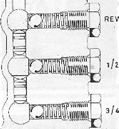
Figure 3.29. Sectional view of the retaining structure.
24. Install the speedometer drive and secure it in the correct position with a special locking clamp (see photo 8.24a, b and c).
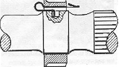
Figure 6.30. Speedometer drive mounting clamp.
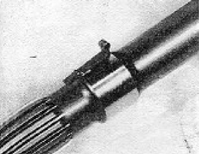
Photo 8.24a. Speedometer drive clamp.
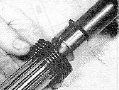
Photo 8.24b. Installing the speedometer drive gear.
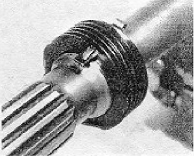
Photo 8.24c. Speedometer drive gear mounted on the shaft.
25. Install the end cover onto the transmission housing using a new gasket and making sure the cover is seated correctly with the magnet facing towards the rear of the transmission (see photos 8.25a and b).
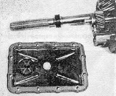
Photo 3.25a. Gearbox cover and gasket.
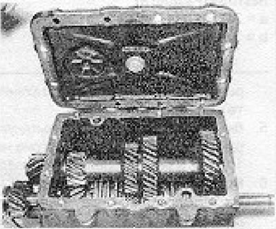
Photo 8.25b. Installing the upper gearbox cover.
26. Before securing the clutch housing to the gearbox, it is necessary to determine the thickness of the washer that must be installed between the clutch housing and the input shaft bearing. Measure the protruding portion of the bearing outer race from the gearbox housing and the depth of the opening in the clutch housing using a special measuring device. Add 0.1 mm to the opening depth and you will get the thickness of the new gasket. Subtract one measurement from the other and the result will be the required washer thickness. Washers are available in four sizes (see photo 8.26).
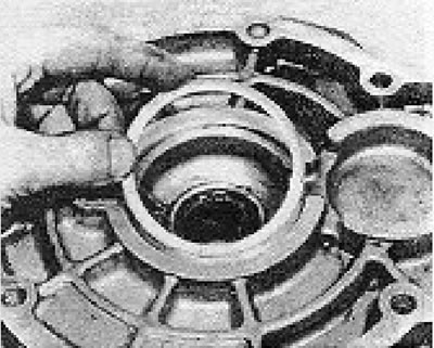
Photo 8.26. Installing the clutch housing washer.
27. Before securing the clutch cover in place, wrap the input shaft cotter pins to prevent damage to the oil seal during installation. Apply putty to the threads of the bolts that go into the gearbox to prevent possible oil leakage (see photo 8.27).
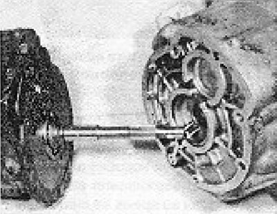
Photo 8.27. Attaching the clutch housing to the gearbox. The shaft cotter pins should be wrapped to protect the seal.
28. Using a new gasket, screw on the clutch cover and tighten the bolts to the required degree (see photo 8.28).
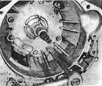
Photo 8.23. Tightening the clutch housing bolts.
29. Install the bearing and clutch release lever as described in Chapter 5.
30. Using a new gasket, install the gearbox extension in place, being careful not to damage the seal lips with the main shaft cotter pins. When inserting the extension into place, insert the selector pin into the slots of the selector lever pawl. All gears must be in neutral position (see photo 8.30).
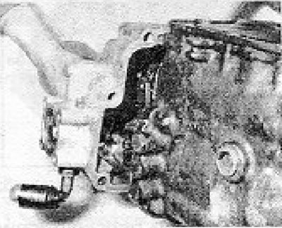
Photo 3.30. Attaching the extension to the gearbox housing.
31. Apply putty to the bolt threads to prevent oil leakage and tighten them. Tighten the bolts to the required degree (see photo 8.31).
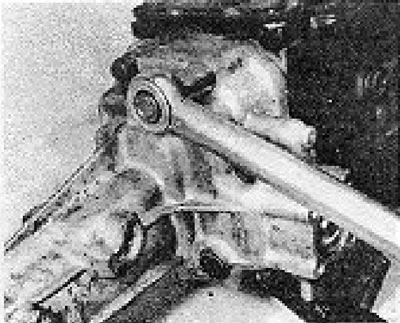
Photo 8.31. Tightening the casing mounting bolts.
Visitor comments