



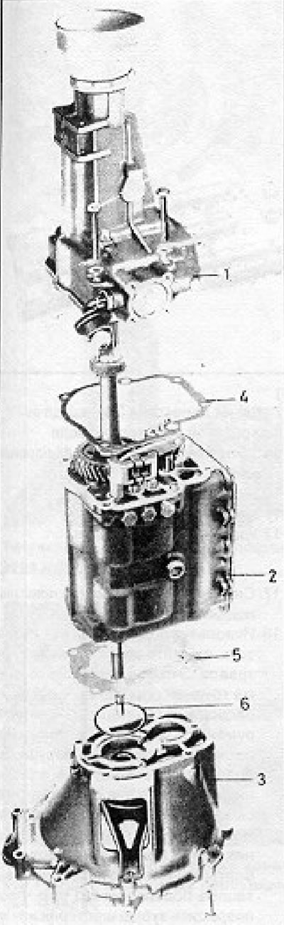
Figure 6.8. Gearbox Housing Sections (Section 5): 1 - Theft; 2 - Gearbox casing; 3 - Clutch housing; 4 - Gasket; 5 - Gasket; 6 - Washer.
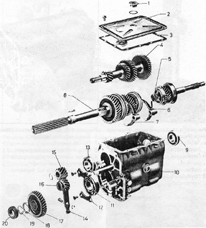
Figure 6.9. Detailed view of the gearbox (Section 5): 1 - Oil drain plug; 2 - Pressed steel bottom cover; 3 - Gasket; 4 - Countershaft; 5 - Input shaft; 6 - 3/4 gear selector fork; 7 - 1/2 gear selector fork; 8 - Main shaft; 9 - Countershaft bearing; 10 - The gearbox casing is transferred; 11 - Main shaft bearing; 12 - Bearing retaining plate; 13 - Countershaft bearing; 14 - Transfer lever; 15 - Countershaft reverse gear; 16 - Idle reverse gear; 17 - Main shaft reverse gear; 18 - Washer; 19 - Spring clamp; 20 - Speedometer drive.
1. After removing the gearbox and draining the oil, clean off any external dirt using paraffin and a stiff brush. or water and detergent.
2. Place the gearbox on a clean workbench, loosen and remove the flange bolts and disconnect the extension from the main housing.
3. Remove the gasket and discard it.
4. Remove the clutch release bearing and lever as described in Chapter 5.
5. Tap the input cotter pins (primary) shaft to prevent damage to the seal lips, then roll up and remove the clutch cover from the gearbox.
6. Save the washer located between the clutch housing and the bearing.
7. Remove and discard the old gasket.
8. Unscrew and remove the oil pan and its gasket from the bottom surface of the gearbox.
9. Remove the spring retaining clip from the rear end of the main shaft and slide the speedometer drive off the shaft. Note that the threaded end of the drive faces the rear end of the shaft.
10. Remove the clamp (b) and pull out the transmission lever pin (see Figure 6.10).
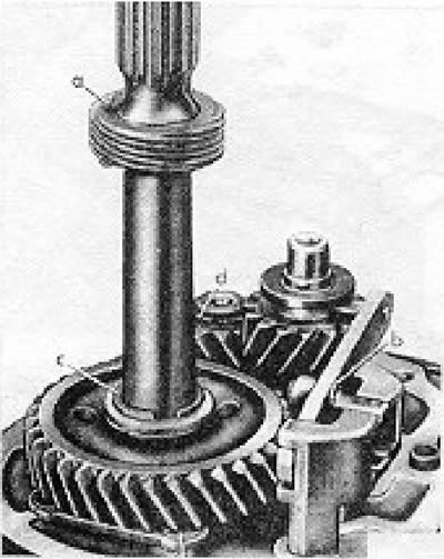
Figure 6.10. Rear of the main shaft: a - Locking lug (speedometer drive); b - Spring clamp (transmission lever); c - Spring clamp (main shaft); d - Spring clamp (countershaft reverse gear).
11. Remove the reverse gear transfer levers.
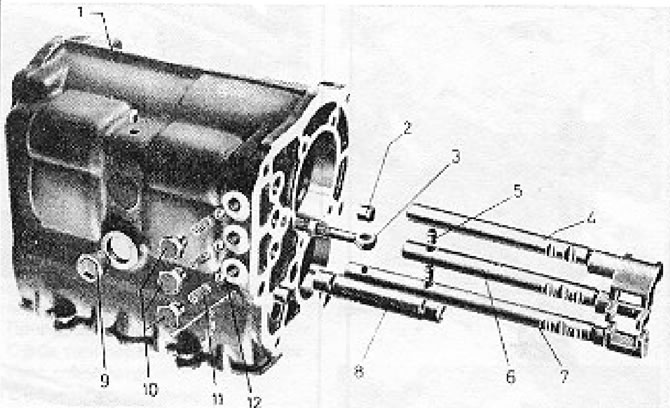
Figure 6.11. Selector details: 1 - Gearbox housing; 2 - Hollow protrusion; 3 - Transfer lever support; 4 - Reverse gear selector lever; 5 - Intermediate pin; 6 - 1/2 gear selector lever; 7 - 3/4 gear selector lever; 8 - Reverse idler shaft; 9 - Oil level/fill hole plug; 10 - Retaining plugs; 11 - Retaining springs; 12 - Retaining balls.
12. Remove the main shaft clamp.
13. Remove the reverse gear washer from the shaft.
14. Remove the reverse gear from the main shaft.
15. Remove the clamp and separate the reverse gear from the counter shaft. Note that the notches on the gear teeth are located closest to the end of the shaft.
16. Remove the screws, they may be very tight and require a special tool to remove.
17. Remove the bearing retaining plates.
18. Using a suitable puller, remove both countershaft bearings. This can be a very difficult operation if you do not have a special tool (6305), and it is better to remove it after breaking the plastic bearing housing, after which three small bolts can be inserted into the holes formed, and nuts can be screwed onto them. If you then attach the bolts to the puller, you can pull the bearing out without damaging the gear teeth or housing. The inner bearing races fit very tightly on the shaft, and trying to remove them from the shaft is useless (see photos 5.18a and b).
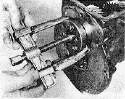
Photo 5.18a. Removing the countershaft bearing.
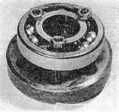
Photo 5.18b. Method of attaching the puller to the bearing.
19. Lift the counter shaft by hand and pull the input shaft out of the housing.
20. Remove the counter shaft, this may require slightly raising the main shaft.
21. Unscrew the plugs two or three turns each.
22. Engage third gear by sliding the 3/4 speed synchronizer sleeve.
23. Remove the roller pin securing the 3/4 speed fork to the selector lever.
24. Pull the 3/4 speed selector lever out until the fork can be disconnected from it.
25. Pull the reverse selector lever out until you can tap out the roller pin securing the 1/2 speed selector lever. Remove the fork.
26. Set all selector levers to neutral position. Be careful not to displace the plungers too far when moving the selector levers. If the plungers have shifted, return them to their place.
27. Using a press or plastic-headed hammer at the rear of the main shaft, tap the shaft off the bearing until it is possible to pull the shaft rearward and remove the bearing from the housing.
28. Tilt the main shaft and remove it hollowly from the inside of the casing.
29. Wipe the inside surface of the casing to remove any deposits and sediment. Clean the magnet.
30. Remove the oil seal from the clutch housing and install a new one, applying grease to its lips (see photo 5.30).
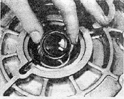
Photo 5.30. Casing oil seal
31. Check that the vent plug is clean.
32. Unscrew and remove the partially released locking plugs, pull out the springs and balls.
The original text can be found at VWMANUAL
33. Remove all selector levers and take out the plungers.
34. If necessary, the reverse idler shaft can be removed from the gearbox housing by screwing a bolt into the threaded hole at its end and using a piece of tubing as a pressure sleeve while tightening this bolt against the thrust washer.
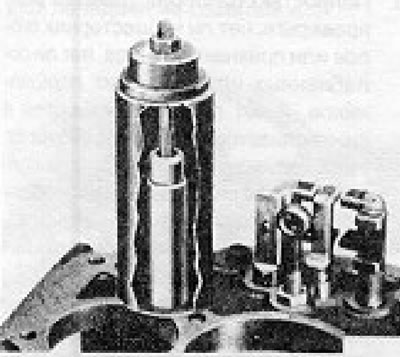
Figure 6.12. Method for removing the reverse idle air filter.
35. If necessary, you can unscrew and remove the transmission lever support from the casing.
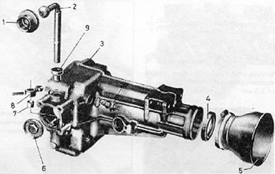
Figure 6.13. Components of the gear shift housing: 1 - Rubber mount; 2 - Inner lever; 3 - Expansion; 4 - Seal; 5 - Dust filter; 6 - End cap; 7 - Inner arm bushing; 8 - Selector lever; 9 - Oil seal bushing assembly.
36. Now pay attention to the expansion of the gearbox. Any wear on the shifter components will require removal of the lever or pin and replacement of the bushings, which can be either unscrewed from their positions or pried off. The finger can be accessed by unscrewing the end cap (see photo 5.36 a and b).
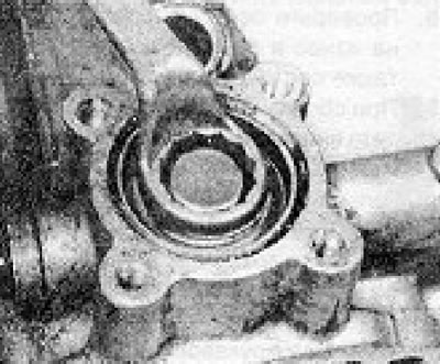
Photo 5.36a. Unscrewing the gearshift mechanism end cover.
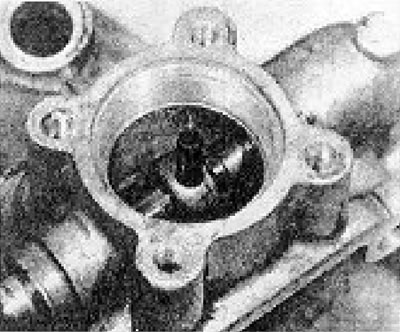
Photo 5.36b. The gear shift finger is shown.
37. Replace the rear expansion joint seal and apply grease to the lips of the new seal.
38. Remove the speedometer drive and gear from the housing extension (see photo 5.38).
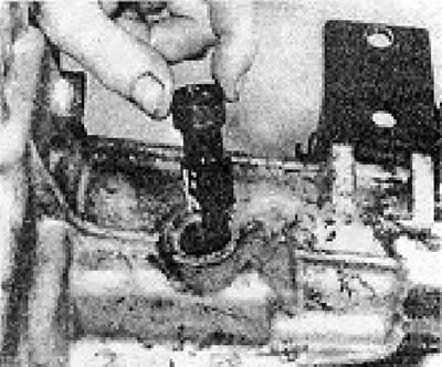
Photo 5.38. Removing the speedometer drive.
39. Once the gearbox is completely disassembled, inspect all gears as described in the following sections. The countershaft cannot be disassembled, and if it is damaged or worn, it will need to be replaced entirely. Replace the countershaft bearings. if they get damaged when removing it.
Visitor comments