
Gear selector
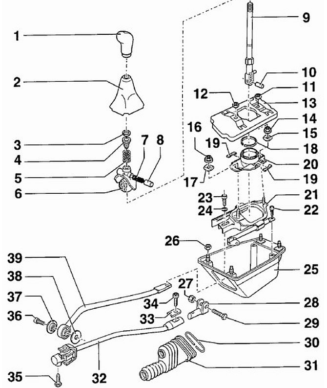
- 1 - handle,
- 2 - protective cover,
- 3 - retaining ring,
- 4 - bushing,
- 5 - spring,
- 6 - ball retainer,
- 7 - spring,
- 8 - bushing,
- 9 - gear lever,
- 10 - intermediate sleeve,
- 11 - nut, 10 Nm,
- 12 - nut, 10 Nm,
- 13 - casing,
- 14 - nut, 25 Nm,
- 15 - special washer,
- 16 - nut, 25 Nm,
- 17 - special washer,
- 18 - retaining ring,
- 19 - damper,
- 20 - body,
- 21 - rear shaft of the gear shift fork,
- 22 - bolt, 10 Nm,
- 23 - bolt, 25 Nm,
- 24 - aiba,
- 25 - body,
- 26 - nut, 10 Nm,
- 27 - self-locking nut, 10 Nm,
- 28 - fork,
- 29 - bolt,
- 30 - compression ring,
- 31 - protective cover,
- 32 - control rod,
- 33 - clamp,
- 34 - bolt, 25 Nm,
- 35 - self-locking bolt, 20 Nm,
- 36 - bolt, 40 Nm,
- 37 - puck,
- 38 - washer,
- 39 - gear lever
Warning: If you want to completely remove the shift mechanism, you must first remove the exhaust system.
Warning: Handle 1 is unscrewed from the gear lever together with the protective cover.
Warning: Spring 7 and sleeve 8 are installed in a ball retainer and mounted on the gear lever so that they are located to the left of the gear lever.
Warning: The spherical side of the sleeve 8 must point towards the gear lever.
Warning: The shift lever 9 can only be installed in one position.
Warning: When installing circlip 18, a new circlip must be used. The convex side of the ring should face the body.
Warning: When installing, a new nut 27 must be used.
Warning: When installing, you must use a new bolt 35.
Warning: When installing, the convex side of the washer 37 must point towards the control lever.
Before making adjustments, check that the gearbox, clutch, shift mechanism and shift linkage are in perfect order. Also check that the shift rods move smoothly and easily.
Order of execution
1. Set the gearshift lever to neutral and apply the handbrake.
2. Detach the lower part of the gearshift boot from the center console.
3. Unscrew from the shift lever and remove it together with the protective cover.
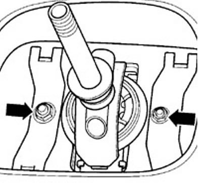
4. Unscrew nuts and remove a rubber casing from the case of the mechanism of a gear change.
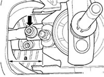
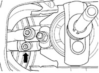
5. measure distance (A) between the body and the gearshift mechanism, which should be 37 mm. If necessary, adjust it as follows. Loosen the screw (arrow) gear shift fork. By moving the shaft, set the required distance and tighten the fastening bolt to a torque of 25 Nm.
6. Loosen the nuts securing the ball joint housing.
7. Install the ball joint housing horizontally.
8. Tighten the ball joint housing nuts to 25 Nm.
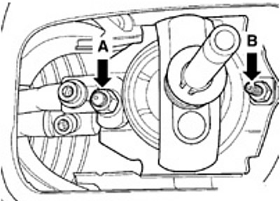
9. Loosen the bolt securing the transmission control rod.
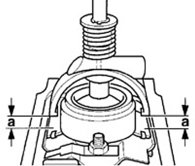
10. Set the gearshift lever to such a position that the protrusions of the ball stop are at the same distance from the body (A).
11. In this position of the gear lever, tighten the gearbox control rod bolt to 25 Nm.
12. Check that the shift lever position has not changed.
13. Check the correct installation of the gear lever. In the neutral position, the gear lever should be set on the third-fourth gear engagement lines.
14. Additional adjustments can be made as follows. Loosen the nuts securing the ball housing. Move the gearshift lever all the way to the right and in this position re-tighten the fastening nuts to a torque of 25 Nm (see point 6).
15. Install and screw on the rubber cover of the gearshift mechanism.
16. Screw the handle onto the shift lever.
17. Attach the shift lever cover to the center console.
18. In this position of the gear lever, tighten the gearbox control rod bolt to 25 Nm.
Visitor comments