
The location and tightening torques of the gearbox mounting bolts on models with a four-cylinder engine
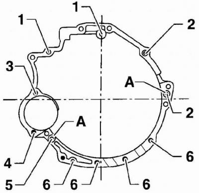
| Position | Bolt | Tightening torque |
| 1 | М12х75 | 65 Nm |
| 2 | М12х110 | 65 Nm |
| 3 | М12х90 | 65 Nm |
| 4 | М12х67 | 65 Nm |
| 5 | M10x135 | 45 Nm |
| 6 | М10х45 | 45 Nm |
| A | Guide bushings | |
The location and tightening torques of the gearbox mounting bolts on models with a five-cylinder engine.
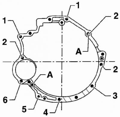
| Position | Bolt | Tightening torque |
| 1 | М12х75 | 65 Nm |
| 2 | М12х130 | 65 Nm |
| 3 | М12х45 | 45 Nm |
| 4 | М12х70 | 45 Nm |
| 5 | M10x60 | 45 Nm |
| 6 | М10х80 | 65 Nm |
| A | Guide bushings | |
The location and tightening torques of the gearbox mounting bolts on models with a six-cylinder engine
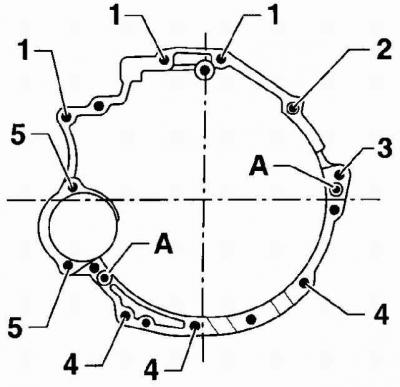
| Position | Bolt | Tightening torque |
| 1 | М12х97 | 65 Nm |
| 2 | М12х90 | 65 Nm |
| 3 | М12х80 | 65 Nm |
| 4 | М12х45 | 45 Nm |
| 5 | M10x135 | 65 Nm |
| A | Guide bushings | |
Arrangement and moments of an inhaling of bolts of fastening of support of a transmission
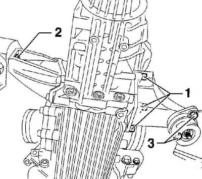
| Position | Bolt | Tightening torque |
| 1 | M10x30 | 40 Nm |
| 2 | M10x35 | 40 Nm |
| 3 | M8x20 | 20 Nm |
Warning: Transmission housings can be made from either aluminum or magnesium alloy. If the gearbox housing is made of magnesium alloy, there is an inscription Mg Al 9 Zn 1 near the oil drain plug. If a magnesium alloy gearbox is installed on the car, it is necessary to coordinate all parts connected to the gearbox, including the gearbox mounting bolts, which must be covered with a special protective layer. If the parts connected to the magnesium alloy gearbox housing are not coordinated, the housing will corrode.
Order of execution
1. Check the condition of the clutch.
2. Clean the spline of the gearbox input shaft and lubricate with a thin layer of special grease based on molybdenum disulphide.
Warning: The lubrication layer must be thin and even, as otherwise, when the clutch is operated, excess lubricant will be thrown onto the working surfaces of the clutch, which may interfere with its operation.
3. Apply a light coat of molybdenum disulphide grease to the pushrod head mating with the clutch release lever.
4. Check that guide bushings are installed in the engine block to center the gearbox.
5. Raise the gearbox towards the engine and install the clutch slave cylinder.
6. Move the gearbox towards the engine, while the input shaft of the gearbox should fit into the grooves of the clutch disc. It may be necessary to rotate the engine crankshaft slightly to align the transmission input shaft splines with the clutch disc splines. When installing the gearbox, the input shaft must not hang on the clutch disc.
7. Move the transmission forward so that the clutch housing is seated on the guide bushings of the cylinder block.
8. Insert the bolts securing the gearbox to the engine and at this stage tighten the gearbox mounting bolts to 25 Nm.
9. Install starter.
10. Tighten bolts of fastening of a transmission to the engine the demanded moment.
11. Connect the ground bar to the gearbox.
12. Screw in and tighten in sequence 1, 2, 3 bolts of fastening of support of a transmission, see fig. The location and tightening torques of the gearbox mounting bolts.
13. Remove the gear box jack.
14. Connect the drive shafts to the gearbox.
15. Install the drive shaft guards and secure them with bolts, tightening them to a torque of 20 Nm.
16. Install and screw the 20 Nm torque control rod and the 40 Nm torque shift rod to the gearbox.
17. Connect the tachometer and reversing light electrical connectors to the transmission.
18. Install the exhaust pipe.
19. Install the expansion tank.
20. Install the air pipe with the air flow meter and secure it with clamps.
21. Connect ground wire to battery.
22. Check and, if necessary, top up the oil level in the gearbox.
23. Install the engine top cover.
24. Install the lower engine mudguard.
Visitor comments