



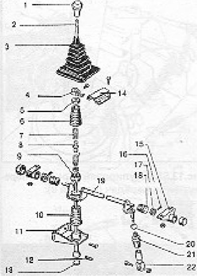
Fig. 13.48. Gear shift mechanism on models with a 2.4 L engine (section 9): 1 - Gear shift knob; 2 - Gear shift lever; 3 - Rubber cover; 4 - Clamping stop; 5 - Adapter; 6 - Rubber cover; 7 - Spring; 8 - Guide sleeve; 9 - Ball; 10 - Rubber cover; 11 - Front bracket; 12 - Threaded pin; 13 - Disc; 14 - Thrust bracket (may be different on models with 4-speed and 5-speed gearboxes); 15 - Support bracket; 16 - Tension sleeve; 17 - Guide sleeve; 18 - Rubber cover; 19 - Gear shift shaft; 20 - Ball; 21 - Rubber cover; 22 - Clamp.
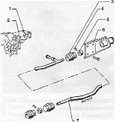
Fig. 13.49. Shift linkage and rear bearing/bracket on 2.4L models (Section 9): 1 - Manual gearbox; 2 - Inner lever; 3 - Rubber cover; 4 - Tension sleeve; 5 - Guide sleeve; 6 - Rear bracket; 7 - Gear shift rod.
9. The gear shift mechanism is adjusted as follows.
(The original information is posted on the website VWmanual.ru)
10. Remove the gear shift knob and rubber boot.
11. Set the lever to neutral position.
12. Adjust the vertical position of the clamp stop on the gear shift lever as shown in Figure 13.50.
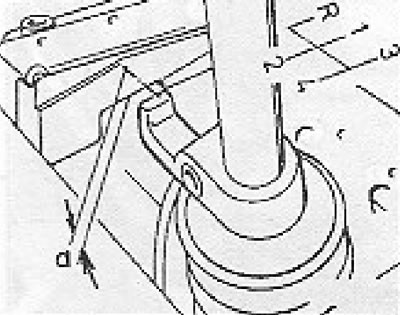
Figure 13.50. Adjusting the clamp stop (Section 9): a = 6 mm
13. Be careful not to press the lever.
14. The clamp stop projection must fit onto the stop bracket without distortion (see photo).
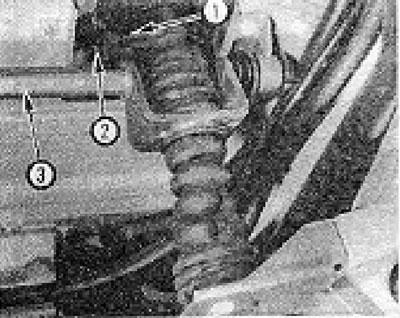
Photo 9.14. Lower end of gear shift lever: 1 - Clamping stop; 2 - Thrust bracket; 3 - Gear engagement rod.
15. Loosen the clamp (see photo).
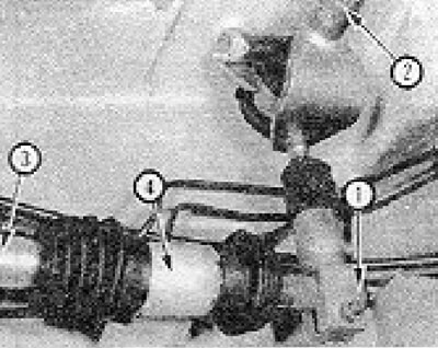
Photo 9.15. Left side of the gear shift rod: 1 - Clamp bolt; 2 - Crosspiece; 3 - Gear shift rod; 4 - Thrust bearing/bracket.
16. Check that the gear shift rod can move freely.
17. Align the gear shift rod and the inner lever shift pin.
18. Move the inner lever down to the 3/4 gear position.
19. Set the gear shift lever to the position shown in the figure 13.51.
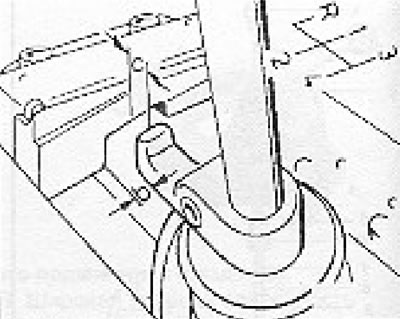
Figure 13.51. Adjusting the gear shift lever (section 9): b = 4 mm; c = 21 mm.
20. Tighten the clamp bolt, install the rubber boot and gear shift knob and check that all gears are engaged.
Visitor comments