



42. Drain the oil from the gearbox.
43. Disconnect the control cable from the lever on the PTO box.
44. Loosen the bolts securing the RTO gearbox to the main gearbox housing and remove the RTO gearbox.
45. Installation of the RTO box is carried out in reverse order. The circumferential clearance between the 3rd gear pinion on the intermediate shaft and the driven gear in the PTO box must be adjusted to the value specified in the Specifications.
46. This is achieved using adjusting linings that are inserted between the PTO box housing and the main box housing.
47. Install the RTO box with adjusting shims of the minimum overall thickness specified in the Specifications.
48. Remove the main gearbox pan.
49. Measure the circumferential clearance between the gears using a dial gauge (see Figure 13.55).
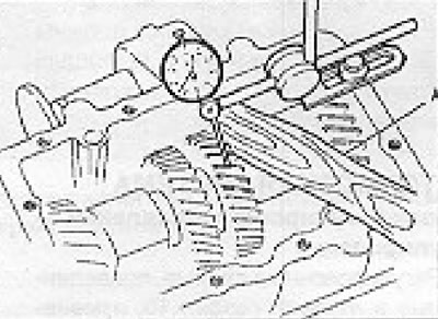
Figure 13.55. Measuring the circumferential clearance of the 3rd gear on the intermediate shaft (section 9): A - The sliding gear should be held using the hammer handle.
50. Adjust the clearance to the value specified in the Specifications using adjusting shims.
Visitor comments