



37. Move the lever forward so that it presses against the stop.
38. Simultaneously transfer to the outside (counterclockwise) lever on the RTO box so that it fits into its retainer.
39. While holding the levers in this position, tighten the clamping screw.
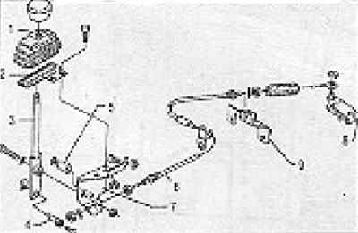
Figure 13.53. Gearbox control cable PTO (section 9): 1 - Case; 2 - Frame; 3 - Lever; 4 - Finger; 5 - Stop; 6 - Cable; 7 - Lever plate; 8 - Gearbox lever; 9 - Bracket.
The original text can be found at [VWManual]
Visitor comments