



33. The RTO gearbox is bolted to the side of the main gearbox and is driven from the main gearbox through a clutch by means of a sliding intermediate gear.
34. The RTO gearbox is engaged and disengaged using a cable-operated lever located in the cabin. A manual throttle is also installed there, allowing you to control the speed of rotation of the drive shaft of the RTO box.
35. The operation of the RTO gearbox must be carried out in accordance with the instructions supplied with it.
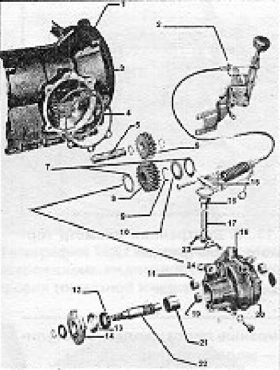
Figure 13.52. Power Take Off gearbox design (section 9): 1 - Intermediate shaft of the gearbox; 2 - Switching mechanism; 3 - Adjusting shim; 4 - O-ring with circular cross-section; 5 - Shaft; 6 - Sliding gear; 7 - Thrust washers; 8 - Drive gear; 9 - Retaining ring; 10 - Adjusting shim; 11 - Needle roller bearing of the shift lever; 12 - Output shaft seal; 13 - Protective cap; 14 - Flange; 15 - Gear shift fork lever; 16 - Bushing; 17 - Gear shift fork; 18 - Gear shift fork locking pin; 19 - Small needle roller bearing of the output shaft; 20 - Power Take Off gearbox; 21 - Large needle roller bearing of the output shaft; 22 - Output shaft; 23 - Castle; 24 - Locking sleeve.
Visitor comments