



2. Remove the camshaft (see section 6).
3. Remove the tappets together with their adjusting screws. A tool with a rubber cup, used for lapping valves, may be useful for removing the tappets. The tappets must be laid out in order to avoid any chance of mixing them up during installation.
4. Using a valve spring compressor (valve spring compressor) compress the spring of the first valve so that the crackers can be removed.
5. Remove the spring retainer, two valve springs and either the spring seat (intake valves), or a special Roto-cap socket (exhaust valves).
6. Remove the oil seals from the ends of the guide bushings. When assembling the head, the oil seals must be replaced with new ones.
7. Repeat the above operation for the remaining valves, laying out all the parts in the order they were removed.
8. Using a blunt tool, remove carbon deposits from the cylinder head. Please remember that the head is made of light alloy and is easily scratched.
9. Check that there are no cracks around the bolt holes and that the threads of the holes are not damaged. If any defects are detected, you should consult a specialist.
10. If you suspect cylinder head deformation, you should check the sealing surface of the head using a straight ruler and feeler gauges. Deformation can occur as a result of overheating or improper tightening of the cylinder head.
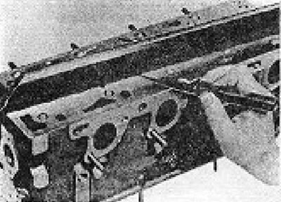
Figure 1.18. Checking the cylinder head for deformation.
11. In case of deformation, the head can be re-ground, provided that its height remains no less than that shown in Figure 1.19.
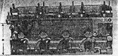
Figure 1.19. Minimum permissible height of the cylinder head: a = 19.5 mm (minimum).
12. Inspect the valve guides for wear. To do this, insert its "native" valve into each bushing (inlet or outlet) and check it for rocking in the bushing. The valve lateral clearance must not exceed the maximum value specified in the Specifications. Ideally, the valve lateral play should be checked using a dial gauge.
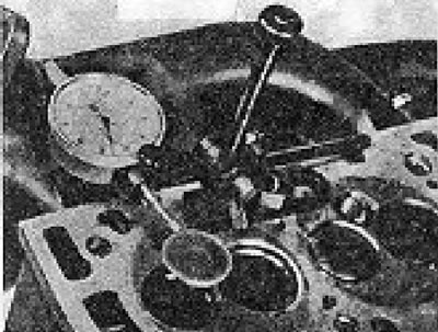
Figure 1.20. Measuring the valve lateral clearance in the guide bushing using a dial gauge.
13. If the wear of the guide bushings exceeds the permissible limits, the bushings must be replaced (produced by a specialist). After replacing the bushings, it is also necessary to install modified valve spring seats.
14. Inspect the valve seats and heads. If they are in good condition and only have small black spots in the area of the sealing surfaces, they can be brought into order by grinding.
15. If they are badly burnt, you should either replace the valves or regrind the intake valves (exhaust valves cannot be reground, they can only be replaced).
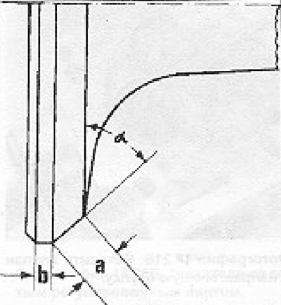
Figure 1.21. Intake valve regrinding diagram: a = 3.5 mm (maximum); b = 0.5 mm (minimum); = 45°.
The valve seats can be re-cut in accordance with Fig. 1.22 and 1.23.
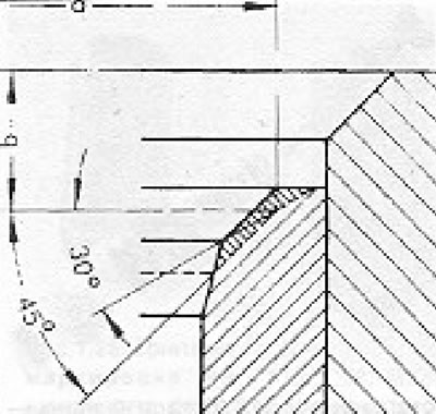
Figure 1.22. Diagram of re-cutting the intake valve seat: a = 36.5 mm (maximum diameter); b = 3.5 mm (maximum); Saddle width 2.0 mm.
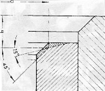
Figure 1.23. Diagram of re-cutting the exhaust valve seat: a = 31.5 mm (maximum diameter); b = 3.9 mm (maximum); Saddle width 2.4 mm.
16. If the valves and their seats are in good condition, they can be brought into order by grinding.
17. To grind the valves, install the cylinder head on the camshaft bearing cap studs.
18. Install the valve lapping tool on the first valve, lubricate the valve stem with oil and apply a small amount of coarse lapping paste to the chamfer of its head. Insert the valve into its guide bushing and use semi-rotary movements to grind the valve head onto the seat. Gradually, the rough texture of the paste will no longer be felt, after which you should remove the valve and wipe it clean. If black spots and discolored areas are still visible on the valve head and seat, the lapping procedure should be repeated until they disappear. To speed up the grinding process, you can put one drop of kerosene on the paste on the valve seat. There should not be too much kerosene, otherwise the paste may get into the guide bushing, which will lead to the most negative consequences.
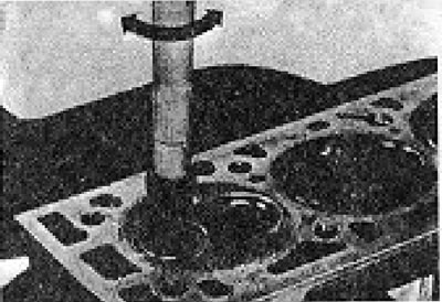
Figure 1.24. Valve grinding.
19. After achieving the desired result with the coarse-grained paste, move on to lapping using the fine-grained paste. Properly lapped valves should have a shiny grey ring on the head. The valve seats should have the same 1.5 mm wide rim.
20. Repeat the lapping procedure on the remaining valves and carefully remove all traces of paste from the valves and seats using kerosene and a brush
21. Begin assembling the head by lubricating the first valve with oil and inserting it into the guide sleeve (see photos).
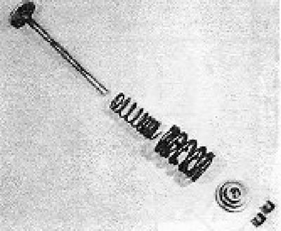
Photo 18.21A. Valve parts - the valve itself, springs, valve plate and crackers. The spring seat or special Roto-cap seat is not shown.
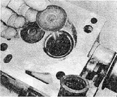
Photo 18.21B. Insert the valve into the guide sleeve.
22. Install the valve stem seal onto the guide sleeve (see photos).
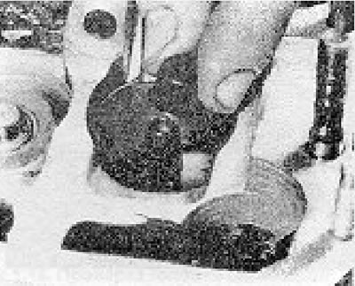
Photo 18.22. Install the valve stem seal using a special plastic mounting sleeve.
To avoid damaging it on the sharp edge of the guide sleeve, use the plastic guide included with the new valve stem seal kit.
23. Install the spring seat (in case of an inlet valve) or a special Roto-cap socket (in case of an exhaust valve) (see photos).
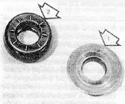
Photo 18.23A. Inlet valve spring seat (1) and special Roto-cap seat (2).
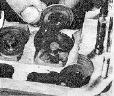
Photo 18.23B. Installing the intake valve spring seat.
24. Install 2 valve springs with the side with closely spaced coils towards the spring plate. If the valve springs have been used for more than 64,000 km, it is recommended to replace them (see photo).
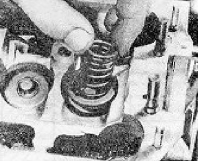
Photo 18.24. Installing the inner valve spring.
25. Install the spring plate. Compress the springs and install the crackers into the groove on the valve stem. Secure the crackers in place with thick grease (see photos).
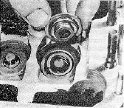
Photo 18.25A. Installing the valve spring retainer.
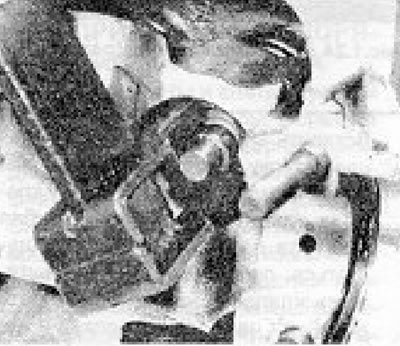
Photo 18.25B. Installing valve springs using a valve spring compressor.
26. Slowly release the valve spring compressor and remove it from the valve.
27. Repeat the above procedure on the remaining valves. Once they are installed, tap the stem of each valve with a hammer (placing a wooden block) in order to seat the valve parts in place. (Before doing this, you should check that there is enough space under the cylinder head to avoid damaging the valves).
28. Lubricate and install the tappets. In this type of tappets, valve clearances are adjusted using special screws(see photos).
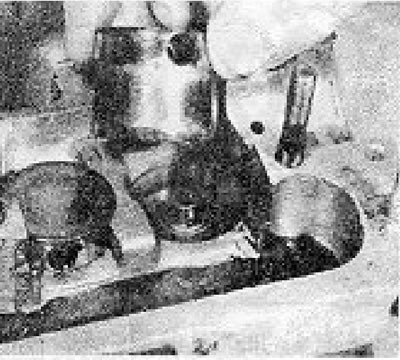
Photo 18.28A. Installing the tappets.
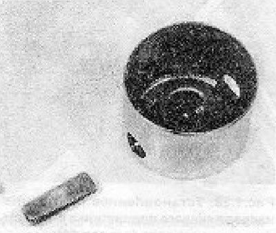
Photo 18.28B. Tappet with adjusting screw removed.
Old style screws have blue, red or yellow markings that correspond to the notched markings on new style screws and tappets as follows:
- Blue marking: 1 notch
- Red marking: 2 notches
- Yellow marking: 3 notches
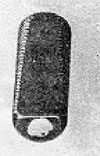
Figure 1.25. Color markings on the valve clearance adjustment screw.
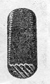
Figure 1.26. Marking notches on the screw for adjusting the valve clearance.
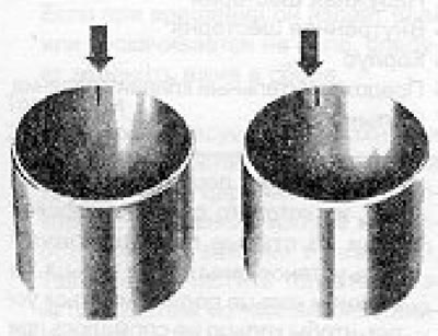
Figure 1.27. Markings on the pushers.
29. On the latest models, the screws may have 1, 2, 3 or 4 notches.
30. If you have re-cut the valve seats, you will need to replace the adjusting screws with simple ones (unmarked) (part no. 046 109 453C).
31. Install the camshaft (see section 6).
32. Adjust the valve clearances (see distributed 20).
33. Install the intake manifold with the carburetor, replacing the gaskets with new ones (see photos).

Photo 18.33A. Installing the intake manifold gasket.
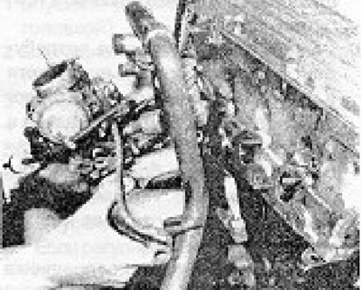
Photo 18.33B. Installing the intake manifold together with the carburetor.
34. Install a new exhaust manifold gasket and then the manifold itself together with the hot air intake shroud (see photo).
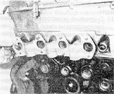
Photo 18.34A. Installing the exhaust manifold gasket.
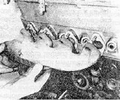
Photos 18.34B. Installation of the exhaust manifold.
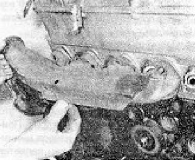
Photo 18.34C. Installation of the hot air intake casing.
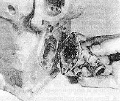
Photo 18.35. Installing the rear elbow of the cylinder head cooling system.
Visitor comments