



Contents: Crankshaft and bearings ↓ Cylinders ↓ Pistons and piston rings ↓ Camshaft and camshaft bearings ↓ Timing belt and sprockets ↓ Pushers ↓ Connecting rods ↓ Flywheel and starter ring gear ↓ Oil pump ↓ Seals and gaskets ↓
1. After completely disassembling the engine, clean all parts and inspect them for wear and damage. Inspection and cleaning of the cylinder head are discussed in the previous section.
Crankshaft and bearings
2. Inspect the surfaces of the connecting rod and main journals for wear and scratches. Using a micrometer, check the crankpins in several places for ovality. If the ovality is more than 0.0254 cm, the necks must be re-ground. The journals also need to be re-ground if they are heavily scratched or worn. Check the main journals in a similar manner.
3. Regrinding of the crankshaft and installation of new bearings must be performed by a specialist.
4. Failure of the connecting rod bearings is indicated by a knocking sound in the engine crankcase area and a slight drop in oil pressure. Failure of the main bearings is accompanied by engine vibration, which can significantly increase with increasing speed. Inspect the connecting rod and main bearings, as well as the thrust washers, for general wear, abrasion and scratches. Bearings should be matte grey in colour. Clearly visible traces of copper indicate severe wear of the bearings (the underlying layer of indium protrudes from under the lead). Unless the bearings are practically new, they should be replaced regardless of their condition.
5. Crankshaft main bearings are manufactured to accommodate oversize main journals of 0.25, 0.50, and 0.75 mm. Regrinding of the journals and installation of oversize bearings are performed in the workshop.
b. If necessary, the connecting rod journals can also be reground to the same size as the main journals. Connecting rod bearings of the required size must be installed in the workshop.
7. Inspect the needle roller bearing in the center of the crankshaft rear flange. If it is worn out or makes noise when rotating, the bearing needs to be replaced (see photo).
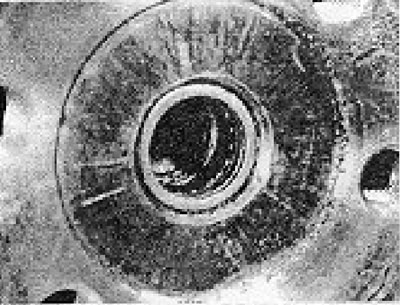
Photo 19.7. Needle bearing in the rear flange of the crankshaft.
8. To replace a bearing, you will need an expanding puller, although in principle you can fill the bearing hole with thick grease and drive a metal rod into it. close in size to the hole. The bearing should be forced out by hydraulic pressure.
9. When installing a new bearing, make sure that its letter marking is facing outward, and drive it inward using a tube resting on the outer ring of the bearing so that it is 1.0 mm below the surface of the crankshaft flange.
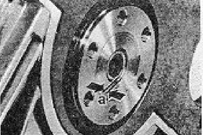
Figure 1.28. Installed position of the guide bearing in the rear flange of the crankshaft (section 19): a = 1.0 mm.
Cylinders
10. Cylinders should be inspected for loss of shape, abrasion and scratches. The inspection should begin from the upper part of the cylinders. If there are ridges corresponding to the top point of the piston stroke, this indicates wear of the cylinders. Signs of excessive wear of the cylinders and piston rings include increased oil consumption and a blue tint to the exhaust gases.
11. Measure the inside diameter of the cylinders just below the ridges and compare it with the diameter at the bottom of the cylinders, not subject to wear. If the difference between the two measured values exceeds 0.152 mm, it is necessary to install special pistons and piston rings, or have the cylinders rebored and then install oversize pistons. If you don't have an internal micrometer or dial gauge, you can use pistons by removing the piston rings and installing them in the original cylinders so that they are approximately 19 mm below the surface of the cylinder block. If the feeler gauge fits 0.254 mm between the cylinder wall and the piston on the thrust side, the following measures must be taken.
12. The repair dimensions of the pistons are indicated in the Specifications. These dimensions are selected to ensure the required working clearance of the piston in the cylinder of the corresponding repair size.
13. If the cylinders are not worn enough to require reboring, special oil scraper rings and pistons can be installed, which will restore compression and prevent oil burning in the engine. There are different types of special oil scraper rings available and the manufacturer's instructions must be strictly followed when installing them.
14. When installing new pistons without boring the cylinders, it is necessary to remove the hard glassy deposits on the cylinder walls using fine-grained sandpaper. This is necessary for proper grinding of new piston rings.
15. New pistons must be checked for fit in the cylinders. To do this you will need a feeler gauge and a spring scale. Insert the feeler gauge between the cylinder wall and the piston and use a spring balance to check the force required to pull the feeler gauge out. To remove a probe with a width of 12.7 mm and a thickness of 0.0025 mm, a force of 3.2 - 4.5 kg should be required.
Pistons and piston rings
16. If you are not going to change the pistons, you should remove the rings from them and clean them thoroughly. The piston ring grooves should be cleaned especially carefully. Be careful not to scratch the aluminum the pistons are made of. If new rings are to be installed on old pistons, the top ring must have a shoulder to prevent the ring from breaking when it hits the ridge at the top of the cylinder (the new ring is not worn "under the ridge" as is the case with the old ring).
Camshaft and camshaft bearings
17. Carefully inspect the camshaft bearings for wear. If they are obviously worn or defective, the cylinder head will have to be replaced, since the camshaft bearings do not have replaceable liners.
18. The camshaft itself should not have any obvious signs of wear. If the cams are badly scratched, the only solution is to replace the camshaft.
19. Inspect the helical gear for wear, chipped teeth and other damage.
Timing belt and sprockets
20. Inspect the timing belt for cracks, wear or damaged teeth. If there are obvious defects, the belt should be replaced.
21. If the belt has been used for more than 64,000 km, it is recommended to replace it regardless of its condition.
22. Inspect the teeth of the crankshaft and camshaft sprockets for wear. If wear is evident, replace the camshaft sprocket and crankshaft sprocket assembly with the pulley.
The original material is available on the portal [vwmanual]
23. Inspect the belt tension pulley. If it makes noise when rotating or wobbles on the shaft, the pulley assembly should be replaced.
Pushers
24. Inspect the bearing surfaces of the tappets. If there are cracks or scratches on them, this indicates serious wear and the need to replace the tappets. Thoroughly clean the inside of the tappets, removing any accumulated sediment. It is highly unlikely that the side surfaces of the tappets will also be worn, however, if the tappets have a lot of play in their channels and are wobbling in them, they should be replaced with new ones. Generally speaking, tappets rarely wear out and are only likely to wear out at very high mileage.
Connecting rods
25. The lateral clearance of the connecting rod installed on the crankpin should not exceed 0.4 mm (measured with a feeler gauge). It is highly unlikely that the side clearance will exceed the specified value, but if this does happen and you replace the crank with a new one, you should check that it is the same weight as the old crank.
Flywheel and starter ring gear
23. If the friction surfaces of the flywheel are scratched by the rivets of the clutch driven disc (which was not but time replaced) or if the ring gear teeth are worn or chipped, the flywheel assembly with the ring gear must be replaced.
Oil pump
27. To disassemble the oil pump, unscrew the countersunk head screws and remove the pump support plate (see photo).
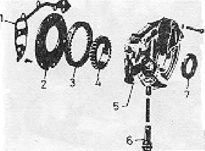
Figure 1.29. Oil pump disassembled (section 19): 1 - Gasket; 2 - Support shield; 3 - External gear; 4 - Internal gear; 5 - Body; 6 - Pressure relief valve; 7 - Seal.
28. Inspect the pump gears for chipped teeth and measure the circumferential clearance of the gears. If the value is outside the specified limits, the gears or the pump assembly should be replaced.
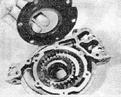
Photo 19.27. Oil pump with the support shield removed.
29. Check the axial clearance of the gears using a ruler and feeler gauges. The axial clearance must correspond to the specified one. Remove the pressure relief valve and inspect it for wear and spring damage (see photo).
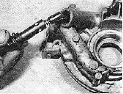
Photo 19.29. Removing the pressure relief valve.
Seals and gaskets
30. Seals and gaskets must be replaced at every engine overhaul, regardless of their condition.
Visitor comments