



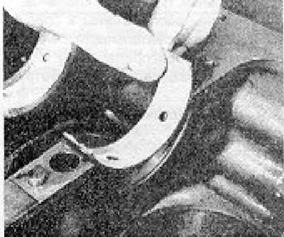
Photo 21.1A. Installing the main bearing shell into the crankcase.
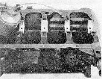
Photo 21.1B. Lubricate the bearing shells.
2. Install the liners with lubrication holes into the crankcase, and the liners without lubrication holes into the main caps. An exception is the central bearing, which has a liner installed in the cover that also has lubrication holes (see photos).
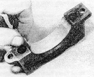
Photo 21.2A. Installing the liner into the main bearing cap.
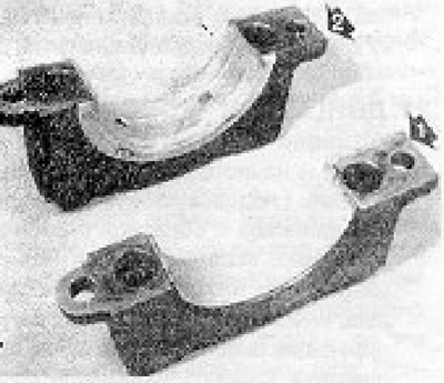
Photo 21.2B. Intermediate (1) and central (2) main bearing caps.
Make sure that the lids and the backs of the liners are free of dirt. Lower the crankshaft into place (see photo).
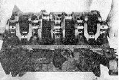
Photo 21.2C. Installing the crankshaft.
3. Lubricate the main journals with oil and install the main bearing caps No. 1 and No. 4 so that their numbers are visible from the oil filter side (see photo).
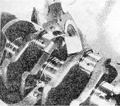
Photo 21.3. Installing the central main bearing cap.
4. Tighten the cover bolts to the required torque.
5. Check the axial movement of the crankshaft by turning it all the way first in one direction and then in the opposite direction, and using a dial gauge or feeler gauge inserted on one side of the central main bearing (see photo).
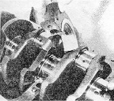
Photo 21.5. Checking the axial movement of the crankshaft.
6. If the axial displacement of the crankshaft does not exceed the specified limits, you can continue assembling the engine. If it is too large, then the thrust flanges of the central knee bearing liners are worn beyond the permissible limits.
7. Lubricate the lips of the new rear crankshaft oil seal and install it on the end of the crankshaft (see photo).
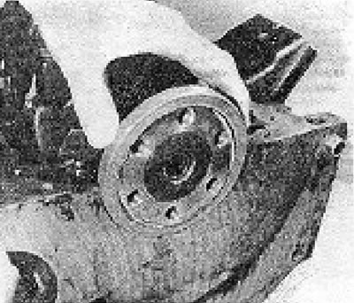
Photo 21.7. Installing the rear crankshaft oil seal.
8. Install the rear main bearing cap, applying sealant to the surface adjacent to the cylinder block. Screw in and tighten to the specified torque first the Allen screw and then the Allen head screws (see photos).
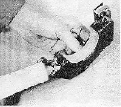
Photo 21.8A. Apply sealant to the rear main bearing cap.
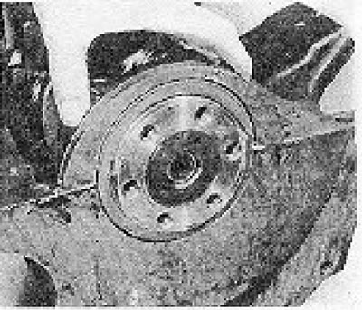
Photo 21.3B. Installing the rear main bearing cap of the crankshaft.
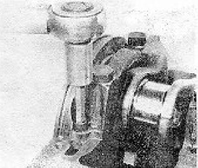
Photo 21.8C. Tightening a hex head screw. fastening the rear main bearing cover.
9. Install pistons and connecting rods (see section 9).
10. Install a new oil pump seal and a new gasket on the front surface of the engine. Secure the oil pump in place with bolts, ensuring that the drive pins fit into the holes in the pump driven ring.
(The original can be viewed on the portal: VWmanual)
11. Install and bolt the oil pickup tube with a new gasket and lock plate. Bend the tabs of the locking plate (see photo).
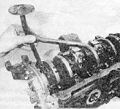
Photo 21.11. Installing the oil intake pipe.
12. Install the pan with new side gaskets and end sealing strips. Apply sealant to the corners where the gaskets and strips overlap (see photos).
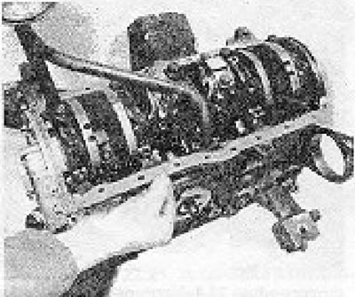
Photo 21.12A. Side pan gaskets.
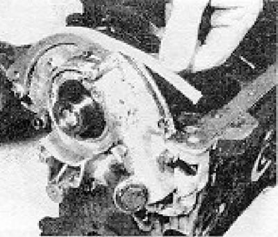
Photo 21.12B. End sealing strips of the pallet.
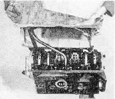
Photo 21.12C. Installing the tray.
13. Install the engine support brackets (if they were filmed).
14. Apply grease to the lips of the oil pump seal and install the timing belt pulley/sprocket (see photo).
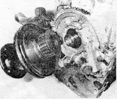
Photo 21.14. Installing the crankshaft pulley/sprocket.
15. Screw in the pulley mounting bolt, having first applied a thread locking compound to its threads. While tightening the bolt, hold the crankshaft from rotating using a lever inserted between the two bolts screwed into the rear flange of the crankshaft (see photo).
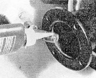
Photo 21.15. Apply thread locking fluid to the crankshaft pulley bolt.
16. Install the flywheel, aligning the marks made during its removal. Lock the starter ring gear (how it was done when removing the flywheel). Apply thread locking compound to the flywheel bolt threads, insert the bolts and tighten them to the specified torque (see photos).
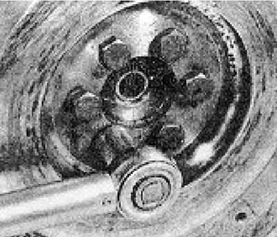
Photo 21.16. Tightening the flywheel bolts.
17. Install the clutch, centering its driven disc as described in Chapter 5.
18. Install the cylinder head (see section 7) and timing belt (see section 5).
19. Install the generator and water pump (see photo).
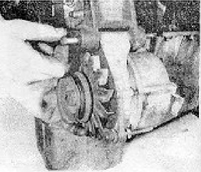
Photo 21.19. Generator support bracket and bolt.
20. Install the drive belt and tighten it (see chapter 2). Install the distributor (see chapter 4)
21. Install the oil dipstick tube (see photo).
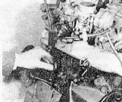
Photo 21.21. Installing the oil dipstick tube.
Visitor comments