



2. Remove the tray (see section 8).
3. Inspect the top of the cylinders for protrusion caused by wear. If there is a protrusion, it should be carefully removed with a scraper to avoid damaging the piston rings when removing the pistons.
4. While working under the machine, check that the numbers on the connecting rod bearing caps match the numbers on the connecting rods (see photo).
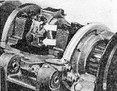
Figure 1.5. Marks on the connecting rod cap.
The base of the lids also has markings in the form of dots indicating the sequence of their installation (counting from the timing belt).
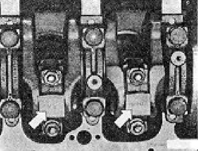
Figure 1.6. Marking indicating the order of connecting rod caps.
The small protrusions on the covers should point towards the timing belt (see photo).
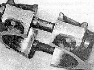
Photo 9.4. Matching numbers on the connecting rod and connecting rod cap.
5. There is an arrow on the piston bottoms. which should point towards the timing belt, but there are no numbers on them.
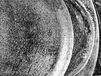
Photo 9.5. Arrow on the piston bottom indicating its position during installation.
Before removing the pistons, it is necessary to mark them with numbers from 1 to 4 using quick-drying paint (starting from the timing belt side) (see photo).
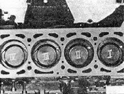
Figure 1.7. Numbers on the piston crowns.
6. Bend back the tabs of the locking plate, unscrew the bolts and remove the oil pump oil intake pipe.
7. Turn the crankshaft so that the lower heads of the connecting rods are in the lower position, and unscrew the connecting rod cap bolts. Remove the first cover together with the connecting rod bearing shell.
8. Push the piston with the connecting rod out through the top of the cylinder.
9. If you do not intend to replace the connecting rod bearing shells, they must be secured with adhesive tape to the corresponding connecting rod heads or caps to avoid confusion later.
10. Remove the remaining 3 pistons with connecting rods in a similar manner.
11. Piston rings are removed through the piston crown. Insert 3 old feeler gauges under the rings, trying hard. so that they are spaced approximately equally apart from each other. This will prevent you from breaking the rings when removing them and will prevent the lower rings from falling into the empty grooves under the upper rings (see photo).
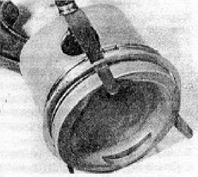
Photo 9.11. Removing piston rings.
12. In order to disconnect the piston from the connecting rod, it is necessary to pull out the piston pin. To do this, remove the retaining rings and then immerse the piston in hot water (60°C). After a few minutes, you can push out the piston pin manually and separate the piston from the connecting rod.
13. The procedure for inspection and tidying up of pistons and cylinders is specified in section 19.
14. Before installing the piston rings on the piston, check that the grooves on the piston are clean. Use a broken piston ring to remove carbon deposits from the grooves. Clean the oil return holes in the grooves (see photo).
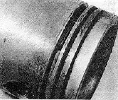
Photo 9.14. Oil return hole in the piston ring groove.
15. Insert each compression ring one by one into its cylinder so that it is no further than 15.0 mm from the bottom edge of the cylinder. and check the gap in the ring lock using a feeler gauge. Compare the obtained figures with the values specified in the Specifications.
16. Install the lower piston (oil scraper) ring and then the top 2 (compression), i checked that the TOP inscription on the compression rings was on top (when viewed from the piston bottom). Compression ring #2 has a ledge that should face down (see photos).
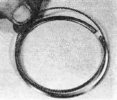
Photo 9.16A. Details of the oil scraper piston ring.
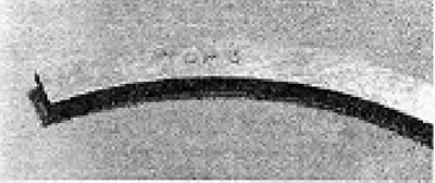
Photo 9.16B. Marking on the compression ring.
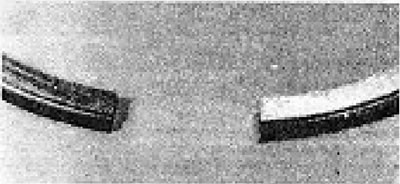
Photo 9.16C. Recess on the second compression ring.
17. Install the piston on its connecting rod, checking that when the arrow on the piston bottom points towards the timing belt, the marking numbers on the connecting rod are on the left side of the engine (from the intake manifold side).
18. Install the piston pin (preheat the piston again) and secure it with two new retaining rings.
19. Wipe clean the bearing seats in the small end of the connecting rod and in the connecting rod cap and install the liners. If you have not changed the liners, check that they go back to their original places when installed (see photos).
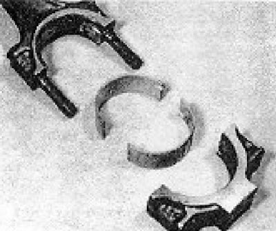
Photo 9.19A. Details of the lower connecting rod head.
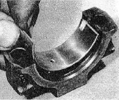
Photo 9.19B. Installing the bearing shell into the connecting rod cap.
20. Install the piston ring compressor on the first piston and check that the piston rings and the inner surfaces of the cylinders are well lubricated with oil.
21. Insert the connecting rod into the cylinder and lower it so that the base of the piston ring compressor rests without tilting on the upper surface of the cylinder block.
22. Place the wooden handle of the hammer against the bottom of the piston and then sharply strike the head of the hammer with your hand. The piston and connecting rod must enter the cylinder, leaving the piston ring compression device on the surface of the cylinder block.
23. Pull the connecting rod down, lubricate the connecting rod journal with oil, install the small head of the connecting rod on it and then the connecting rod cap. Screw on the cover nuts and tighten them to the required torque (see photos).
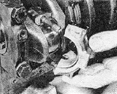
Photo 9.23A. Installing the connecting rod cover.
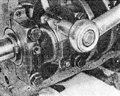
Photo 9.23B. Tightening the connecting rod cap nuts.
24. Install the three remaining pistons with connecting rods in a similar manner, turning the crankshaft if necessary to move the required connecting rod journal to the most convenient position for connecting the connecting rod.
25. Install the oil pickup tube with a new gasket and lock plate. Tighten the tube bolts and secure them by bending the tabs of the locking plate.
26. Install the tray (see section 8).
27. Install the cylinder head (see section 7).
28. Fill the engine with oil.
Visitor comments