



2. Drain the coolant (see chapter 2).
3. Disconnect the negative cable from the battery (the battery is located behind the left seat).
4. Remove the camshaft cover.
5. Remove the timing belt (see section 5).
6. Disconnect the low voltage wire that runs between the ignition coil and the distributor (see photo).
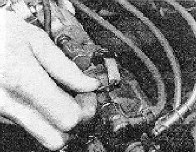
Photo 7.6. Disconnecting the low voltage wire from the distributor.
7. Disconnect the high tension wire running between the ignition coil and the center of the distributor cap (see photo).
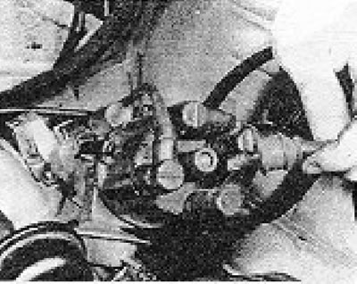
Photo 7.7. Disconnecting the wire connecting the ignition coil to the distributor cap.
8. Disconnect the wire from the oil pressure switch, which is screwed into the rear surface of the cylinder head.
9. Disconnect the wire from the cooling system thermal switch, which is screwed into the elbow on the rear surface of the cylinder head.
10. Remove the water hose from the knee.
11. Disconnect the brake booster vacuum hose from the intake manifold.
12. Disconnect the fuel supply hose from the carburetor and plug it.
13. Disconnect the gas pedal cable from the carburetor.
14. Disconnect the wiring from the automatic choke and the air cut-off solenoid valve located on the carburetor. Some very early models are fitted with a choke control which operates in conjunction with a corresponding warning light on the instrument panel. In this case, you need to disconnect the choke cable from the lever on the carburetor.
15. Unscrew the nuts and disconnect the exhaust downpipe from the exhaust manifold.
16. Disconnect the water hoses from the thermostat housing. Disconnect the hoses going to the front end of the intake manifold (see photos).
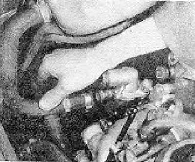
Photos 7.16A. Disconnecting the hoses from the thermostat housing.
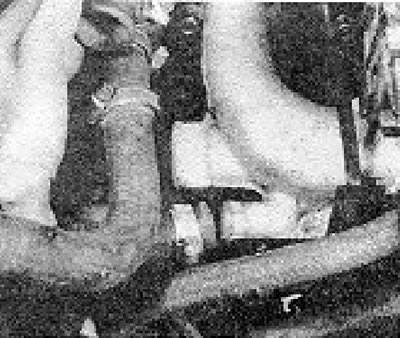
Photo 7.15B. Disconnecting the water hoses from the intake manifold.
17. Disconnect the intake manifold stand and the crankcase ventilation hose (see photo).
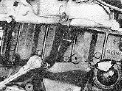
Photo 7.17. Intake manifold stand and crankcase ventilation outlet (shown by the arrow).
18. Loosen and remove the cylinder head bolts, starting with the center bolts and gradually moving toward the edges of the head, loosening the bolts 1/4 turn at a time. The cylinder head bolts have a hex key hole and require a special wrench for removal.
19. Remove the head from the cylinder block, using the intake manifold as a lever to rock the head if it is not moving properly.
20. Remove the cylinder head gasket (when installing the head, it must be replaced with a new one).
21. If you plan to clean the head from carbon deposits and grind the valves, see section 18. If the head was removed to replace a blown cylinder head gasket, the contact surfaces of the head and block should be thoroughly cleaned and any dirt should be removed from the combustion chambers.
(The original can be found at VWmanual.ru)
Remember that the head is made of light alloy and is very easy to damage.
22. Install a new gasket on the cylinder block, making sure that the bolt holes, water jacket channels, oil channels and mounting pins are aligned (see photo).
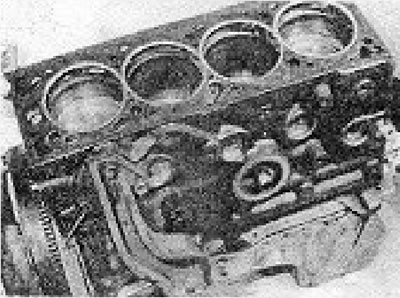
Photo 7.22. Installing the cylinder head gasket.
23. Turn the crankshaft so that the TDC marks on the flywheel and clutch housing or the marks on the crankshaft pulley and oil pump are aligned.
24. Turn the camshaft sprocket so that the mark on its rear surface aligns with the mark on the camshaft cover.
25. Lower the cylinder head onto the dowel pins and tighten its bolts evenly to the specified torque in the sequence shown in the figure 1.4 (see photos).
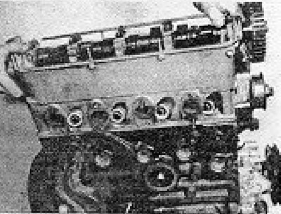
Photo 7.21A. Installing the cylinder head.
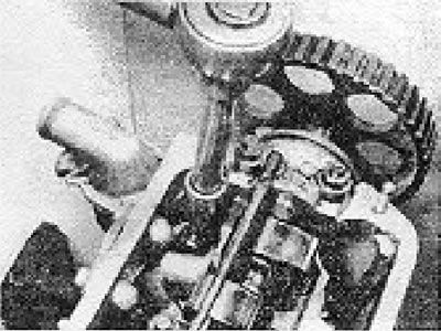
Photo 7.25B. Tightening the cylinder head bolts.
26. Connect all hoses, drive mechanisms and electrical wiring.
27. Install the timing belt (see section 5).
28. Install the camshaft cover with new end gaskets and sealing strips.
29. Connect the wire to the battery.
30. Install the air cleaner.
31. Fill the cooling system with liquid (see chapter 2).
32. Replace the engine cover.
Visitor comments