



The overhead camshaft is driven by a toothed belt from a sprocket located at the front end of the crankshaft. The crankshaft rests on 5 main bearings with replaceable liners. The central bearing shell has thrust flanges to control the axial movement of the crankshaft.
Each piston has 2 compression rings and one oil scraper ring. The pistons are connected to the connecting rods using piston pins, which are secured with retaining rings. The valve mechanism has a conventional design, however the exhaust valves are equipped with special Roto-cap spring seats, while the intake valves have conventional spring seats.
Valve clearances are adjusted using special screws located in the tappets.
The lubrication system uses a gear oil pump, bolted to the front surface of the cylinder block and driven by the crankshaft.
The oil pump includes a pressure relief valve. A full-flow oil filter is installed on the right side. Low oil pressure warning light switch (oil pressure relay) mounted on the rear surface of the cylinder head (see photo).
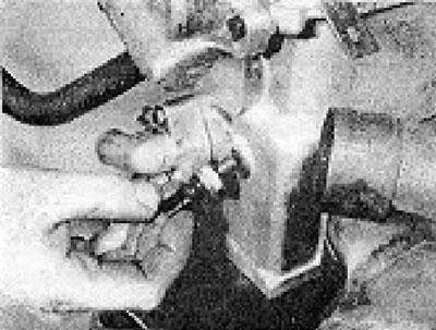
Photo 1.0. Oil pressure switch.
The cylinder head and sump are made of light alloy, and the crankcase and cylinder block are made of cast iron.
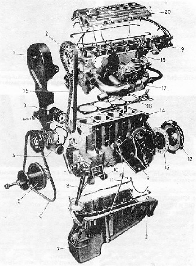
Figure 1.1. Main engine components (section 1): 1 - Timing belt cover; 2 - Camshaft sprocket; 3 - Oil filter; 4 - Water pump; 5 - Crankshaft pulley timing belt sprocket; 6 - V-belt; 7 - Pallet; 8 - Oil intake pipe; 9 - Engine support bracket; 10 - Generator mount; 11 - Oil dipstick; 12 - Clutch pressure plate assembly; 13 - Clutch driven disc; 14 - Crankcase/cylinder block; 15 - Timing belt; 16 - Cylinder head gasket; 17 - Intake manifold; 18 - Cylinder head; 19 - Distributor; 20 - Camshaft cover.
Visitor comments