



2. Disconnect the negative cable from the battery.
3. Drain the coolant (see chapter 2) into some container (if you are going to reuse it).
4. Remove the radiator and air duct (see chapter 2).
5. Loosen the bolts and remove the fan from the crankshaft pulley.
6. Remove the bolts securing the exhaust pipe bracket to the gearbox.
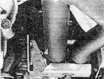
Figure 1.8. Mounting bolts (4) of the exhaust pipe bracket.
7. Check the bolts securing the exhaust downpipe to the exhaust manifold.
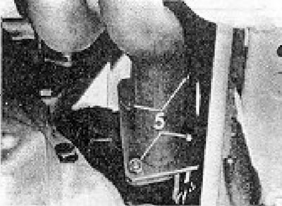
Figure 1.9. Flange nuts (5) of the exhaust system downpipe.
8. Unscrew and remove the oil filter.
9. Unscrew the starter mounting bolts, remove the starter without disconnecting the wiring from it, and place it in the driver's cabin.
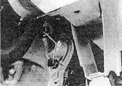
Figure 1.10. Starter mounting bolts (6).
10. Disconnect the electrical connector at the rear of the generator (see photo).
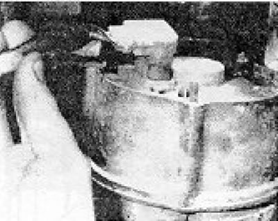
Photo 15.10. Generator wiring.
11. Unscrew and remove the bolts securing the engine to the clutch housing, leaving the topmost bolt in place at this stage. Remove the lower front clutch housing cover.
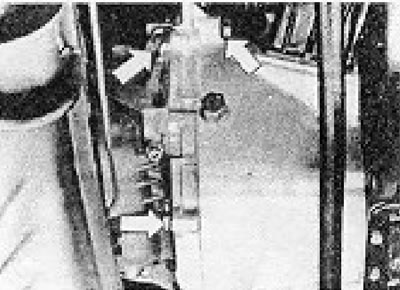
Figure 1.11. Clutch housing bolts.
12. Support the gearbox with a jack or hang it as shown in the figure 1.12.
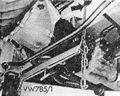
Figure 1.12. Gearbox support cradle (vW 785/1 tool) (section 15).
13. Remove the expansion tank together with its support bracket and the water hoses leading to the thermostat housing and the intake manifold (see photo).
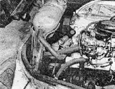
Photo 15.13. Removing the expansion tank bracket screw.
14. Remove the air cleaner (see chapter 3) together with the air intake duct and its elbow. Disconnect the exhaust gas aftertreatment system hose (if available, see chapter 3).
15. Disconnect the gas pedal cable from the lever on the carburetor. Pull out the C-clamp and disconnect the cable from the support bracket. Disconnect the manual choke control cable (if there is one) (see photo).
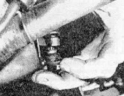
Photo 15.15. The gas pedal cable clamp near the support bracket.
16. Disconnect the wires from the carburetor air shut-off valve and from the automatic choke unit (if any).
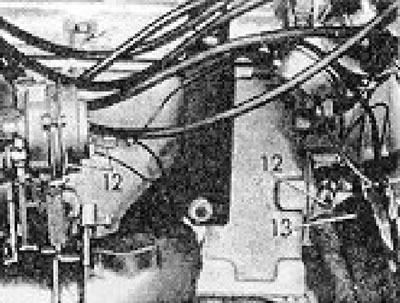
Figure 1.13. Electrical wires and hoses: 12 - Automatic suction and temperature sensor; 13 - Heater hose at the elbow on the cylinder head.
17. Disconnect the wires from the temperature sensor and oil pressure switch.
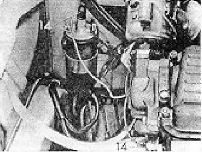
Figure 1.14. Ignition coil and oil pressure relay wires (14).
18. Disconnect the high voltage wire from the ignition coil or the central terminal on the distributor cap and the low voltage wire from the distributor or the negative terminal of the coil.
19. Disconnect the heater hose from the water pump.
20. Disconnect the brake servo vacuum hose from the intake manifold.
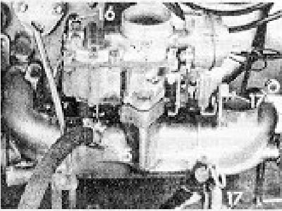
Figure 1.15. Connection points for the brake servo booster vacuum hose (15), fuel supply hose (16) and gas pedal cable (17).
21. Disconnect the fuel supply hose from the carburetor (in case of an electric fuel pump) or from the fuel pump (in case of a mechanical fuel pump) and tighten it. Also disconnect the fuel return hose (if any).
22. Remove the engine weight from the mounts and, working in the driver's cabin, remove the nuts from both engine mounts (the very top nuts that are visible when looking down at the engine). Raise the engine like this. so that the support brackets come off the studs.
23. Remove the upper clutch housing bolt, previously left in place.
24. Move the engine forward away from the gearbox so that the gearbox drive shaft disengages from the clutch.
25. Lift the engine, turn it around and remove it from the driver's cabin.
Visitor comments