



2. Valve clearances on a cold engine differ from valve clearances on a warm engine. After the initial clearances have been set on a cold engine, be sure to check them when the engine has warmed up. The correct valve clearance values are given in the Specifications.
3. Remove the camshaft cover. Turn the crankshaft pulley (or camshaft if the cylinder head is removed from the engine) so that both cams for cylinder No. 1 point upward at approximately the same angles.
4. Insert the feeler gauge between the cam and the tappet. The feeler gauge should have a tight sliding fit. If this is not the case, turn the pusher so that the hole for the screw is visible and insert an Allen key into it. To adjust the clearance, turn the screw one or more full turns. With each full turn of the screw, the valve clearance will change by 0.05 mm. A click will be heard at the end of each turn (see photos).
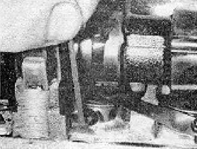
Photo 20.4A. Checking valve clearance.
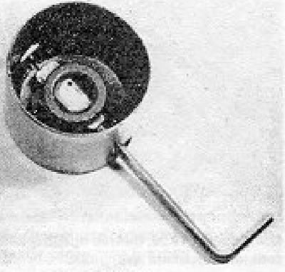
Photo 20.4B. Valve clearance adjustment screw and Allen key inserted into the tappet.
5. Once the adjustment is complete, remove the hex key and insert the special tool in its place. The wall of the pusher must pass within the part of the tool that has notches (see Figure 1.30).
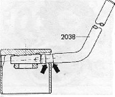
Figure 1.30. Special tool (2038) for checking the position of the adjusting screw in the tappet (section 20).
If this is not the case, the screw should be replaced with a larger one (screw of the next size) and adjust the gap again.
6. Repeat the above operation on the remaining three pairs of valves.
The information is presented on the website (vwmanual)
7. The valves are arranged in the following sequence (counting from the timing belt):
- 1 - Inlet (with a larger diameter head);
- 2 - Graduation (with a smaller diameter head);
- 3 - Inlet;
- 4 - Graduation;
- 5 - Inlet;
- 6 - Graduation;
- 7 - Intake;
- 8 - Graduation.
8. If valve clearance adjustment is performed as part of maintenance, then after its completion it is necessary to replace the camshaft cover gasket with a new one.
Visitor comments