
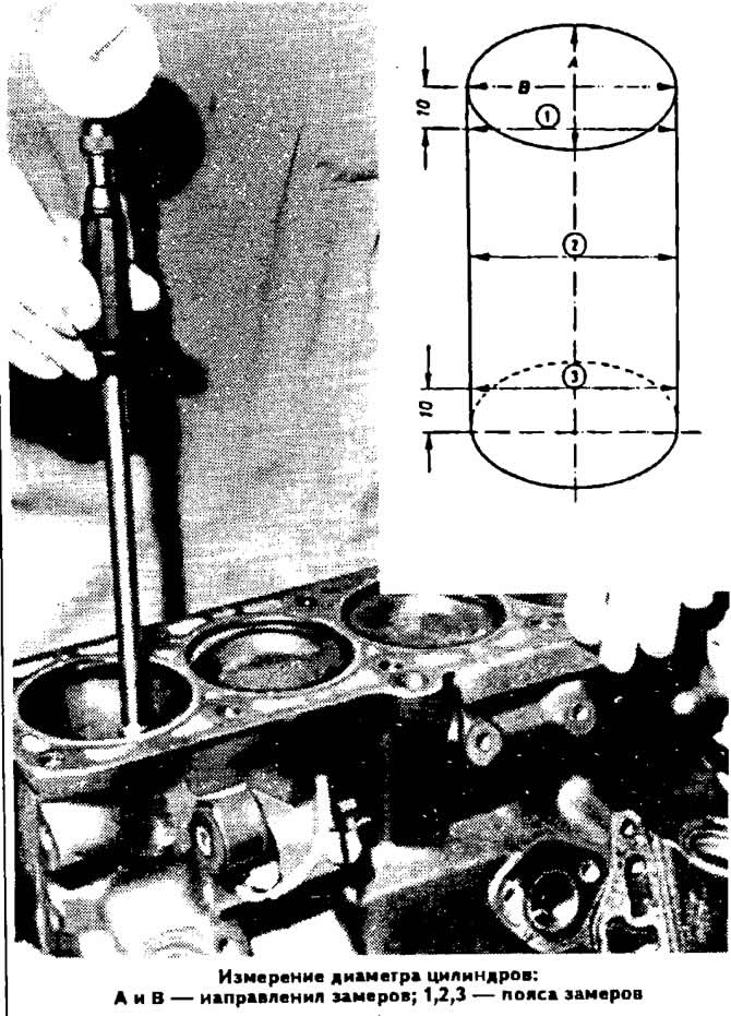
Checking cylinder diameters
Accurately measure cylinder diameters. Measurements to be made with a caliper in three belts as in the transverse direction «A», and in the longitudinal direction «IN», as shown in the diagram.
In cases where wear exceeds the allowable value by more than 0.04 mm, repair the cylinders to the nearest oversize and install pistons of the appropriate oversize.
Checking clearances between liners and crankshaft journals
Thoroughly clean the running surfaces of the liners and the corresponding crankshaft journal. Put a piece of plastic calibrated wire, equal in width to the insert, on the surface of the neck.
Depending on the type of neck to be checked, install a connecting rod with a cap or a main bearing cap on the neck and tighten the fastening nuts or bolts, respectively. First, tighten the nuts of the connecting rod bolts with a torque of 3.0 kgf·m, and then tighten them by 180°, the bolts for fastening the main bearing caps with a torque of 6.5 kgf·m. Do not rotate the engine crankshaft
Carefully remove the cover and, using the scale printed on the package, determine the size of the gap by the flattening of the wire. More details are given in the accompanying documentation of the gauge wire manufacturer.
The nominal design gap is 0.030-0.080 mm (maximum allowable 0.17 mm) for indigenous and 0.015-0.062 mm (maximum allowable 0.12 mm) for crankpins.
If the gap is greater than the limit, then replace the liners on these necks with new ones. If the crankshaft journals are worn out and are ground to a repair size, then replace the liners with repair ones (increased thickness).
Checking the axial clearance of the crankshaft
Check the axial clearance of the crankshaft using a feeler gauge on the middle support, which should be no more than 0.25 mm.
If necessary, achieve proper clearance by using thicker thrust washers.
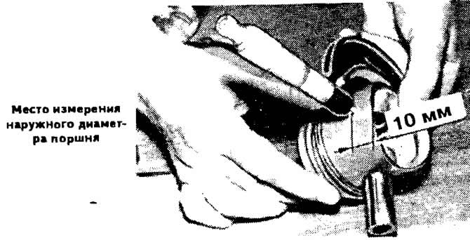
Checking the dimensions of pistons and piston rings
Determine the degree of wear of the piston by measuring the diameter of 10 mm from the edge of the piston skirt perpendicular to the axis of the piston pin. The piston must be replaced if its diameter differs by more than 0.04 mm from the permissible values (see subsection «Design and specifications»).
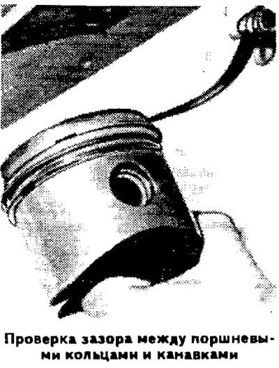
Replace the piston rings or pistons if the gaps between the piston rings and grooves exceed the allowable values (see subsection «Design and specifications»).
Engine Assembly
The 1st, 2nd and 5th main bearing shells do not have oil grooves. The 3rd bearing shells supplied as spares have collars. On the thrust half-rings from the axial displacement of the crankshaft on the side of the cylinder block there is a protrusion directed to the liner.
Install three piston rings into the corresponding grooves in the pistons, placing their locks through 120°.
Orient the piston ring locks forward or backward in the direction of the vehicle. There is a mark on the lower compression and oil scraper rings «top» or «oben» («top»), which must face upwards when the ring is installed in the groove.
Install the pistons, orienting the arrow pressed out on the bottom of the piston, forward in the direction of the car (towards the camshaft drive).
Lubricate pistons and piston rings with engine oil, compress the piston rings in the grooves with a suitable mounting sleeve and insert the pistons with connecting rods into the cylinders.
Install the liners in the connecting rods and connecting rod caps in accordance with the marks made during disassembly, if worn liners are used.
Install the connecting rods and covers on the crankshaft journals, while the sagging on the covers and the locking tabs on the liners should be directed towards the intermediate shaft.
Screw on the nuts of the connecting rod bolts, then tighten them to a torque of 3.0 kgf·m and tighten them by 180°.
Install the rear oil seal holder with a new cardboard gasket. Using tool 2003/1, press the oil seal into the holder.
Install the flywheel, ensuring that the surface under the clutch disc protrudes relative to the cylinder block within 30.50-32.10 mm.
If necessary, install a spacer between the flywheel and the crankshaft flange. Install the lock washer on the flywheel with the beveled edge toward the flywheel. Apply special glue to the fastening bolts.
Install the crankshaft front oil seal retainer with a new cardboard gasket. Press a new oil seal into the holder using drift 3083.
Insert the intermediate shaft into the cylinder block. Install the holder with pressed-in oil seal and gasket on the intermediate shaft.
Install the oil pump after checking its technical condition.
Install the oil pan with a new gasket.
Install the cylinder head.
Install the camshaft drive belt.
Install water pump.
Visitor comments