



Contents: Removal ↓ Installation ↓
Steering column switches are lever switches for the direction indicator/high beam and windshield wipers, mounted on the steering column.
Removal
1. Disconnect the battery.
Caution: Observe safety precautions when handling air bags.
2. Remove the steering wheel airbag, see the relevant chapter.
3. Align the wheels so that they are set to drive straight ahead and remove the steering wheel, see the relevant chapter.
4. Remove the steering column trim, see the relevant chapter.
5. Unscrew bolt 1 under contact spiral 4 (see illustration).
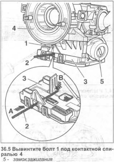
6. Insert a drill 2 or a suitable wire with a diameter of 2.5 mm into the hole on the steering column control unit 3, pushing it to a depth of approximately 45 mm (see arrow A in Illustration 36.5). This is how the internal stopper is released (see arrow B).
7. Use a screwdriver to press the locking tab on the back of the control unit 3 (see arrow in illustration).
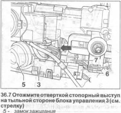
8. Disconnect the control unit from the steering column by pushing it downwards.
9. Disconnect plug 6 on the control unit (see illustration 36.7).
10. Remove the locking clip on plug 7 and disconnect the plug from the control unit (see illustration 36.7).
Attention! When installing the unit, make sure that the contact pins of the plugs are not bent. The plugs themselves must be fixed when connected, which is accompanied by a clearly audible click.
11. Raise the stopper leashes up a little (see arrows in the illustration) and disconnect the contact spiral 1 from the steering column.
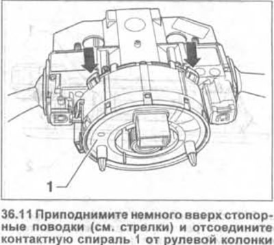
Attention! Do not move the position of the coil. To do this, fix it with tape.
Attention! There is a reference mark on the spiral, which is visible through a small viewing window.
12. Disconnect the steering angle sensor 1 from the steering column switch by pushing it back (see arrow in illustration).
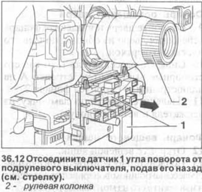
13. Insert a 1.0 mm thick template 1 into the gap between the switch and the coil body and press down the retaining tab (see arrow A in the illustration).
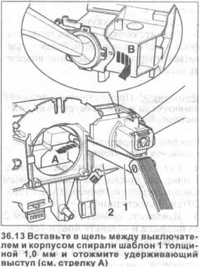
14. Disconnect the steering column switch 2 by pushing it back from the coil housing (see arrow B in illustration 36.13).
15. Disconnect the steering column turn signal switch in the same manner.
Installation
The installation of the steering column switches is performed in the reverse order of removal. The switches should lock into place with a clearly audible click when connected.
When replacing the old steering column switch with a new one, the workshop should perform basic settings. When replacing the control unit, the corresponding code should also be entered (the work is carried out in the workshop).
Visitor comments