
English Русский
Български
Беларускі
Український
Српски
Hrvatski
Română
Polski
Slovenský
Magyar
  |  Articles  |  Sitemap  |  Contacts  |    |
Car maintenance Ford Car maintenance Hyundai Car maintenance Chevrolet Car maintenance BMW Car maintenance Audi Car maintenance Opel Car maintenance AvtoVAZ
VWmanual.ru


Main   Passat   Golf   Polo   Touareg   Tiguan   Sharan   Transporter   Others  
Golf 1 (1974-1984, diesel) Golf 1 (1974-1984, petrol) Golf 2 (1984-1993, petrol) Golf 2 (1984-1993) Golf 3 (1991-1997) Golf 4 (1997-2004) Golf 5 (2003-2008)

Interior Switches — Removal and Installation (Golf) (VW Golf 5)

  • Main
  • Golf
  • Golf 5
  • Electrical equipment
  • Lighting and appliances
  • Interior Switches — Removal and Installation (Golf)
            0


Contents: Hazard warning light switch ↓ Airbag lock ↓ Glove box light switch ↓ Switches on the center console ↓ Driver's door window and rear view…↓ Central lock switch on the driver's…↓ Fuel filler flap lock switch on…↓ Power window switch on the front…↓ Switches on the trim of the central…↓ Steering wheel switches ↓

Hazard warning light switch


Removal


1. Turn off the ignition and remove the key from the ignition switch.

2. Remove the central deflector, see the corresponding chapter.

3. Disconnect the plug located on the back of the deflector cover.

4. Squeeze the two tabs on the back of the deflector trim and disconnect the hazard warning light switch.

The switch is installed in the reverse order of removal.

Airbag lock


Removal


5. Turn off the ignition and remove the key from the ignition switch.

6. Remove the glove box, see the relevant chapter.

Caution: Observe safety precautions when handling air bags.


7. Disconnect the airbag lock connector located on the rear of the glove compartment, release the two locking rods and remove the lock.

The lock is installed in the reverse order of removal.

Glove box light switch


Removal


8. Turn off the ignition and remove the key from the ignition switch.

9. Remove the glove box, see the relevant chapter.

10. Press the two locking leashes and remove the switch.

The switch is installed in the reverse order of removal.

Switches on the center console


Removal


11. Turn off the ignition and remove the key from the ignition switch.


12. Release the corrugated cover from its mounting on the centre console and place it over the gearshift lever, see the relevant chapter.

13. Remove the pocket or ashtray on the centre console, see the relevant chapter.

14. Disconnect the plugs on the back of the switch cover (see arrows in the illustration).
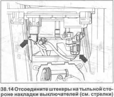
14. Disconnect the plugs on the back of the switch cover (see arrows in the illustration).


15. Press the locking tabs and disconnect the switches.

The switches are installed in the reverse order of removal.

Driver's door window and rear view mirror switches


Removal


16. Turn off the ignition and remove the key from the ignition switch.

17. Remove the door armrest trim using a plastic wedge, see the relevant chapter.

18. Disconnect the plugs on the back of the cover.

19. Press down the four locking clips (see arrows A in the illustration) and remove the window lift switch 1 from the cover.
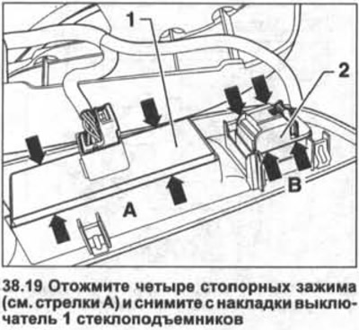
19. Press down the four locking clips (see arrows A in the illustration) and remove the window lift…


20. Press down the four locking clips (see arrows B in illustration 38.19) and remove the switch for 2 rear view mirrors from the cover.


The switches are installed in the reverse order of removal.

Central lock switch on the driver's door


Removal


21. Turn off the ignition and remove the key from the ignition switch.

22. Remove the trim from the driver's door, see the corresponding chapter.

23. Disconnect plug 1 from the back of the door trim (see illustration).
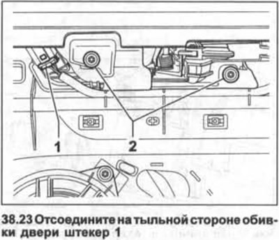
23. Disconnect plug 1 from the back of the door trim (see illustration).


24. Unscrew the two bolts 2 and remove the lock switch button from the door trim (see illustration 38.23).

25. Release the four retaining clips and remove the switch from the door lock button cover.

The switch is installed in the reverse order of removal.

Fuel filler flap lock switch on driver's door


Removal


26. Turn off the ignition and remove the key from the ignition switch.

27. Remove the trim from the driver's door, see the corresponding chapter.

28. Disconnect plug 1 on the rear side of the door trim (see illustration).
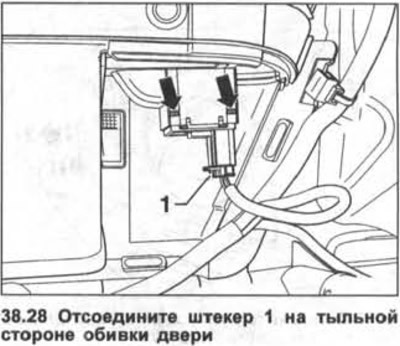
28. Disconnect plug 1 on the rear side of the door trim (see illustration).


29. Press down the two locking clamps (see arrows in illustration 38.28) and remove the switch from the door trim.

The switch is installed in the reverse order of removal.

Power window switch on the front passenger door and on the rear side door


Removal


30. Turn off the ignition and remove the key from the ignition switch.

31. Remove the trim from the door armrest using a plastic wedge, see the relevant chapter.

32. Disconnect the connectors on the back of the door trim.

33. Release the two retaining clips and remove the switch from the door trim.

Attention! Removing the window lift switch on the front and rear doors is performed in the same way as the fuel filler door lock switch (see illustration 38.28).


The switch is installed in the reverse order of removal.

Switches on the trim of the central pillar on the left side of the cabin


Removal


34. Open the door with the remote control to deactivate the security alarm.

35. Turn off the ignition and remove the key from the ignition switch.

36. Using a screwdriver, pry the interior security and towing protection switches out of the center pillar trim on the left side of the passenger compartment.

37. Disconnect the plugs from the removed switches.

The switches are installed in the reverse order of removal.

Steering wheel switches


Removal


38. Disconnect the battery.

Caution: Observe safety precautions when handling air bags.


39. Remove the driver's airbag from the steering wheel, see the relevant chapter.

40. Disconnect plug 1 of the control unit (see illustration).
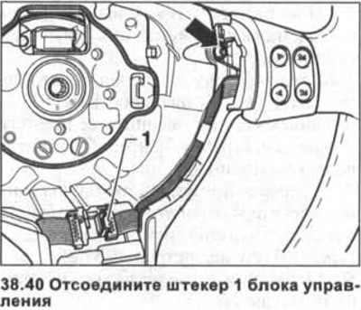
40. Disconnect plug 1 of the control unit (see illustration).


41. Unscrew the bolt (see arrow in illustration 38.40) and remove the switch block from the steering wheel.

The switches are installed in the reverse order of removal.

This article is available at russian, bulgarian, belarusian, ukrainian, serbian, croatian, romanian, polish, slovak, hungarian
The text has been checked: Kolesnikov Artem

Share information:

Previous articles
Light switch — removal and installation
Steering column switches — removal and installation
Instrument cluster — removal and installation
Interior Lights — Bulb Replacement (Touran)
Interior Lights — Bulb Replacement (Golf)
Additional brake light — removal and installation
Next articles
Interior Switches — Removal and Installation (Touran)
Radio receiver — removal and installation
CD changer on the center console — removal and installation
Speakers — Removal and Installation (Golf)
Speakers — Removal and Installation (Touran)
Antenna signal booster — removal and installation


Similar articles from other manuals for VW cars:
Dashboard switches Passat B3 (1988-1993)
Interior switches on the instrument panel Polo 3 (1995-2003)
Interior rear view mirror Tiguan 1 (2007-2015)
Body and interior equipment Transporter T4 (1990-2003)
Car interior lighting Caddy 3 (2003-2010)
Link to this page in different formats


Visitor comments


No comments yet


How much will 14 + 30 =


Golf 5 
  • General information
  • User manual
  • Maintenance
  • Troubleshooting
  • Power unit
  • Engine repair
  • Cooling and ventilation system
  • Fuel system
  • Ignition system
  • Transmission
  • Clutch
  • Mechanical gearbox
  • Automatic gearbox
  • Chassis
  • Brake system
  • Car suspension
  • Steering
  • Body
  • Interior (internal elements)
  • Exterior (external elements)
  • Doors and covers
  • Electrical equipment
  • Power devices
  • Washers and wipers
  • Lighting and appliances
  • Electrical circuits
Golf 4 
  • General information
  • User manual
  • Weekly checks
  • Maintenance
  • Power unit
  • Petrol engines
  • Diesel engines
  • Cooling system
  • Fuel system (petrol)
  • Control system (petrol)
  • Fuel system (diesel)
  • Exhaust system
  • Transmission
  • Clutch
  • Car gearbox
  • Drive shafts
  • Chassis
  • Car suspension
  • Steering
  • Wheels and tires
  • Brake system
  • Body
  • Exterior (external elements)
  • Interior (internal elements)
  • Ventilation and heating
  • Car doors and sunroof
  • Washers and glass cleaners
  • Electrical equipment
  • Power devices
  • Lighting and appliances
  • Electrical circuits
Golf 3 
  • Petrol engine
  • Engine repair
  • Lubrication system
  • Cooling system
  • Ignition system
  • Diesel engine
  • Engine repair
  • Diesel injection system
  • Pre-glow system
  • Transmission
  • Clutch
  • Gearbox and drive shafts
  • Chassis
  • Steering
  • Wheels and suspension
  • Brake system
  • Electrical equipment
  • Lighting and appliances
  • Electrical circuits
Golf 2 
  • General information
  • Introduction to guide
  • User manual
  • Petrol engines 1.3 l
  • Engine repair
  • Lubrication system
  • Cooling system
  • Carburetors
  • Supply system
  • Ignition system
  • Petrol engines 1.6/1.8 l
  • Engine repair
  • Supply system
  • Ignition system
  • Diesel engines
  • Engine repair
  • Lubrication system
  • Cooling system
  • Power and exhaust system
  • Transmission
  • Clutch
  • 4-speed gearbox 084
  • 5-speed gearbox 085
  • 4-speed gearbox 020/4R
  • 5-speed gearbox 020/4T
  • Automatic gearbox
  • Drive shafts
  • Chassis
  • Steering
  • Car suspension
  • Brake system
  • Body
  • Body elements
  • Doors, locks and windows
  • Electrical equipment
  • Equipment and devices
  • Power devices
Golf 2 (petrol) 
  • General information
  • Characteristics
  • Car care
  • Maintenance
  • Power unit
  • Engine repair
  • Engine 1.05/1.30
  • Engine 1.60/1.80
  • Cooling and lubrication system
  • Power and exhaust system
  • Transmission
  • Clutch
  • Car gearbox
  • Drive shafts
  • Chassis
  • Brake system
  • Steering
  • Suspension
  • Body
  • Body and equipment
  • Electrical equipment
  • Lighting and appliances
  • Electrical circuits
Golf 1 (petrol) 
  • General information
  • Characteristics
  • User manual
  • Maintenance
  • Power unit
  • Engine adjustment
  • Engine 1.1/1.3
  • Engine 1.5/1.6/1.8
  • Engine electrical equipment
  • Cooling system
  • Fuel system
  • Transmission
  • Clutch and manual gearbox
  • Automatic gearbox
  • Chassis
  • Steering
  • Front suspension
  • Rear suspension
  • Brake system
  • Electrical equipment
  • Lighting and appliances
  • Electrical circuits
  • Body
  • Body and equipment
  • Optional equipment
Golf 1 (diesel) 
  • General information
  • Specifications
  • Maintenance
  • Power unit
  • Engine repair
  • Exhaust and turbocharger
  • Cooling system
  • Fuel system
  • Fuel injection system
  • Transmission
  • Clutch and drive shafts
  • Car gearbox
  • Chassis
  • Suspension and wheels
  • Steering
  • Brake system
  • Wheels and tires
  • Body
  • Heating and ventilation
  • Exterior (external elements)
  • Interior (internal elements)
  • Doors and windows
  • Electrical equipment
  • Equipment and devices
  • Lighting system
  • Power devices
  • Electrical circuits
VWmanual.ru © 2016-2026 | Mobile version | News and articles | Sitemap: EN BG BY UA RS HR RO PL SK HU | Write message | Site search
Passat B2 • Passat B3 • Passat B4 • Passat B5 • Passat B6 • Golf 1, diesel • Golf 1, petrol • Golf 2, petrol • Golf 2 • Golf 3 • Golf 4 • Golf 5 • Polo 3 • Polo 4 • Touareg 1 • Tiguan 1 • Sharan 1 • Transporter T3 • Transporter T4 • LT 28 • LT 2D • Beetle • Caddy 3 •
Our website uses cookies to ensure functionality and convenience.