
English Русский
Български
Беларускі
Український
Српски
Hrvatski
Română
Polski
Slovenský
Magyar
  |  Articles  |  Sitemap  |  Contacts  |    |
Car maintenance Ford Car maintenance Hyundai Car maintenance Chevrolet Car maintenance BMW Car maintenance Audi Car maintenance Opel Car maintenance AvtoVAZ
VWmanual.ru


Main   Passat   Golf   Polo   Touareg   Tiguan   Sharan   Transporter   Others  
Golf 1 (1974-1984, diesel) Golf 1 (1974-1984, petrol) Golf 2 (1984-1993, petrol) Golf 2 (1984-1993) Golf 3 (1991-1997) Golf 4 (1997-2004) Golf 5 (2003-2008)

Disassembling the shock absorber strut (VW Golf 3)

  • Main
  • Golf
  • Golf 3
  • Chassis
  • Wheels and suspension
  • Disassembling the shock absorber strut
            0


Contents: Removal the lower control arm ↓ Removal the steering knuckle ↓ Removal the wheel bearing ↓ Coil springs and shock absorbers ↓
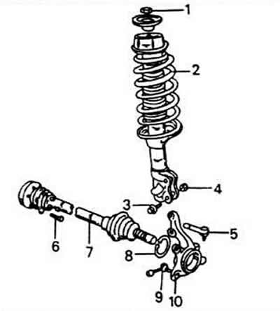
Elements of the front shock absorber strut together with the drive shaft and wheel bearing housing:

Elements of the front shock absorber strut together with the drive shaft and wheel bearing housing:
1 - self-locking nut, 60 Nm
2 - shock absorber strut
3 - for connecting the shock absorber strut to the steering knuckle
4 - nut, 95 Nm
5 - Transverse steering rod
6 - steering knuckle screw, 45 Nm
7 - drive shaft
8 - bearing spring retaining ring
9 - brake seat screw, 125 Nm
10 - wheel bearing housing (swivel pin)
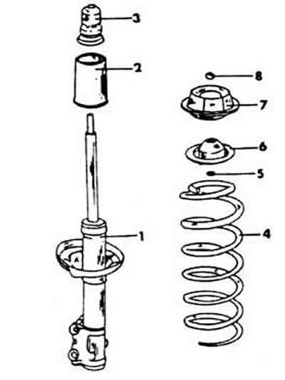

Assembly diagram of the front shock absorber strut:

Assembly diagram of the front shock absorber strut:
1 - shock absorber
2 - protective cuff
3 - rubber stop
4 - coil spring
5 - washer
6 - upper spring seat
7 - shock absorber support
8 - slotted nut


Removal the lower control arm


Completely unscrew the loose shaft nut and remove the washer.

Remove the brake disc from the wheel hub. It is secured with a separate screw.

Press the shaft out of the pivot pin or knock it out with a rubber mallet. If using a press, make sure that the wheel bearing housing is not damaged during this operation.

Remove the nut and screw that secure the wishbone to the underside of the steering knuckle.

Remove the wishbone. If necessary, insert a screwdriver into the slot in the steering knuckle to make it easier to open the steering knuckle.
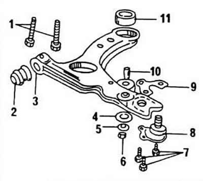
1 - subframe screws, 130 Nm

1 - subframe screws, 130 Nm
2 - front rubber support
3 - transverse lever
4 - rubber bushing for connecting hose of anti-roll bar
5 - shaped washer
6 - Nut for connecting rod of anti-roll bar, 25 Nm
7 - ball joint screws, 35 Nm
8 - suspension support joint
9 - lock washer
10 - spring clamp with safety pin
11 - rear rubber support


The method of fastening the transverse lever is shown in the figure. The position of the rubber bushings is also visible here.

Removal the steering knuckle
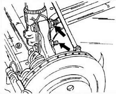


Removal the steering knuckle


Remove the nuts from both steering knuckle screws on the underside of the shock absorber.


Carefully knock out the screws. They may be very tight because their rods are pinched. If the screws need to be replaced, remember that they provide the correct wheel alignment.

Insert a screwdriver behind the mounting flange of the wheel bearing housing and press the housing out of the shock absorber.

Immediately check whether the screw threads have been damaged during knocking out. If this has happened, replace the screws, having first measured the camber.

Removal the wheel bearing
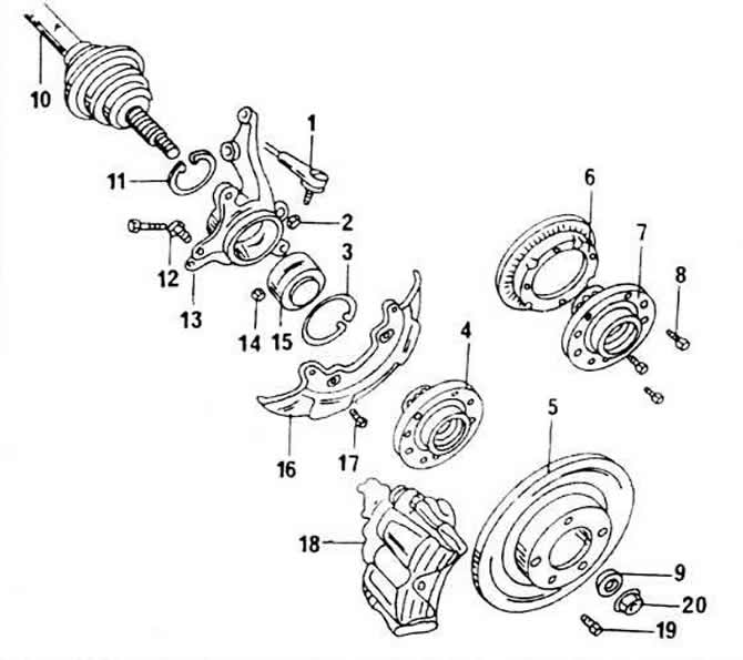


1 - transverse steering rod

1 - transverse steering rod
2 - nut, 50 Nm
3 - bearing spring retaining ring
4 - wheel hub
5 - brake disc
6 - anti-lock braking device ring gear
7 - wheel hub with anti-lock device
8 - screws for fixing the gear ring
9 - thrust disc
10 - drive shaft
11 - spring retaining ring
12 - brake seat screw, 125 Nm
13 - steering knuckle
14 - self-locking nut, 35 Nm
15 - wheel bearing
16 - mudguard
17 - screw, 10 Nm
18 - brake saddle
19 - brake disc screw
20 - hub cap grease


Note the ring bolted to the inside of the wheel hub that is associated with the ABS tachometer.
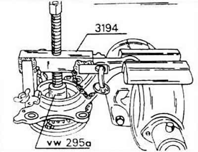
Note the ring bolted to the inside of the wheel hub that is associated with the ABS tachometer.


Place the wheel hub complete with bearing housing and mudguard under a press and carefully press out using a suitable press mandrel. If a two-arm puller is available, the surface journal can be clamped in the press wheel hub from the bearing journal.
Place the wheel hub complete with bearing housing and mudguard under a press and carefully press…


Unscrew the mudguard.

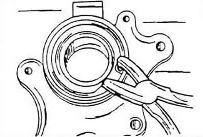
Remove the snap ring located on the inside of the bearing housing, and then remove the outer snap ring.

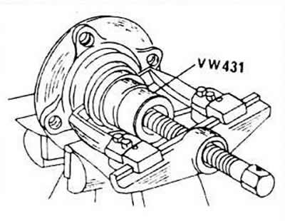
Press out the outer bearing ring, positioning the bearing housing (swivel pin) on the press table so that the mounting flange faces upward.
Press out the outer bearing ring, positioning the bearing housing (swivel pin) on the press table…


The information is posted on this website (www.VWmanual.ru)

The inner bearing ring remains on the wheel hub; it must be removed using a suitable removal tool.
if necessary, unscrew the anti-lock braking device crown from the wheel hub; this is done only when replacing the wheel crown or hub.

Coil springs and shock absorbers
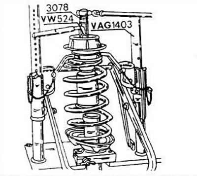


Coil springs and shock absorbers


Using a suitable spring clamp, clamp the spring until all tension in the spring is released.

Remove the nut located in the middle of the upper bearing. This is a splined nut that needs to be removed with a special key (3078). If you cannot get this key, unscrewing the nut can cause serious problems.

Remove the upper shock absorber bearing. You can only replace the entire bearing assembly at once.

Remove the upper spring disc.

Remove the coil springs. There are different groups of tolerances for the dimensions of the springs. The springs themselves are marked with colored stripes. Therefore, when replacing the springs, you must select two of them with the same marking marks. In no case should you install the first springs you come across, since they are designed for a certain engine weight, gearbox, corresponding road stability, etc., parameters that vary for individual models.

Lower the elastic rubber pad from the piston rod of the shock absorber. Pay attention to how it is put on the shock absorber strut, as its ends are different.

Check the operation of the shock absorber. To do this, clamp the lower end in a vice and try to remove and insert the piston rod. The counteraction force should be the same throughout the entire working stroke. If the shock absorber was laid flat, before installation, clamp it in a vice and pump it to remove all the air from it. At the same time, slowly remove the damper and reinsert it until the counteraction becomes uniform. All the air must be released.

This article is available at russian, bulgarian, belarusian, ukrainian, serbian, croatian, romanian, polish, slovak, hungarian
The text has been checked: Medvedeva Elena

Share information:

Previous articles
Dismantling and installation of shock absorber struts
Front Wheel Suspension. General Information
Wheels and tires. General information
Tightening torques for threaded connections of suspension
Technical parameters of the suspension
Next articles
Repair of shock absorber strut
Assembling the shock absorber strut
Dismantling and installation of individual suspension parts
Rear suspension. General information
Removal and installation the rear axle
Dismantling and installation of shock absorber struts


Similar articles from other manuals for VW cars:
Removal and installation the shock absorber / disassembling the… Passat B3 (1988-1993)
Shock absorber strut for Classic, Estate cars Polo 3 (1995-2003)
Removal and installation the shock absorber strut Touareg 1 (2002-2006)
The structure of the shock absorber strut Tiguan 1 (2007-2015)
Coil spring and shock absorber Sharan 1 (1995-2000)
Throttle body Shock Absorber Transporter T4 (1990-2003)
Removal and installation the shock absorber strut Caddy 3 (2003-2010)
Link to this page in different formats


Visitor comments


No comments yet


How much will 21 + 20 =


Golf 5 
  • General information
  • User manual
  • Maintenance
  • Troubleshooting
  • Power unit
  • Engine repair
  • Cooling and ventilation system
  • Fuel system
  • Ignition system
  • Transmission
  • Clutch
  • Mechanical gearbox
  • Automatic gearbox
  • Chassis
  • Brake system
  • Car suspension
  • Steering
  • Body
  • Interior (internal elements)
  • Exterior (external elements)
  • Doors and covers
  • Electrical equipment
  • Power devices
  • Washers and wipers
  • Lighting and appliances
  • Electrical circuits
Golf 4 
  • General information
  • User manual
  • Weekly checks
  • Maintenance
  • Power unit
  • Petrol engines
  • Diesel engines
  • Cooling system
  • Fuel system (petrol)
  • Control system (petrol)
  • Fuel system (diesel)
  • Exhaust system
  • Transmission
  • Clutch
  • Car gearbox
  • Drive shafts
  • Chassis
  • Car suspension
  • Steering
  • Wheels and tires
  • Brake system
  • Body
  • Exterior (external elements)
  • Interior (internal elements)
  • Ventilation and heating
  • Car doors and sunroof
  • Washers and glass cleaners
  • Electrical equipment
  • Power devices
  • Lighting and appliances
  • Electrical circuits
Golf 3 
  • Petrol engine
  • Engine repair
  • Lubrication system
  • Cooling system
  • Ignition system
  • Diesel engine
  • Engine repair
  • Diesel injection system
  • Pre-glow system
  • Transmission
  • Clutch
  • Gearbox and drive shafts
  • Chassis
  • Steering
  • Wheels and suspension
  • Brake system
  • Electrical equipment
  • Lighting and appliances
  • Electrical circuits
Golf 2 
  • General information
  • Introduction to guide
  • User manual
  • Petrol engines 1.3 l
  • Engine repair
  • Lubrication system
  • Cooling system
  • Carburetors
  • Supply system
  • Ignition system
  • Petrol engines 1.6/1.8 l
  • Engine repair
  • Supply system
  • Ignition system
  • Diesel engines
  • Engine repair
  • Lubrication system
  • Cooling system
  • Power and exhaust system
  • Transmission
  • Clutch
  • 4-speed gearbox 084
  • 5-speed gearbox 085
  • 4-speed gearbox 020/4R
  • 5-speed gearbox 020/4T
  • Automatic gearbox
  • Drive shafts
  • Chassis
  • Steering
  • Car suspension
  • Brake system
  • Body
  • Body elements
  • Doors, locks and windows
  • Electrical equipment
  • Equipment and devices
  • Power devices
Golf 2 (petrol) 
  • General information
  • Characteristics
  • Car care
  • Maintenance
  • Power unit
  • Engine repair
  • Engine 1.05/1.30
  • Engine 1.60/1.80
  • Cooling and lubrication system
  • Power and exhaust system
  • Transmission
  • Clutch
  • Car gearbox
  • Drive shafts
  • Chassis
  • Brake system
  • Steering
  • Suspension
  • Body
  • Body and equipment
  • Electrical equipment
  • Lighting and appliances
  • Electrical circuits
Golf 1 (petrol) 
  • General information
  • Characteristics
  • User manual
  • Maintenance
  • Power unit
  • Engine adjustment
  • Engine 1.1/1.3
  • Engine 1.5/1.6/1.8
  • Engine electrical equipment
  • Cooling system
  • Fuel system
  • Transmission
  • Clutch and manual gearbox
  • Automatic gearbox
  • Chassis
  • Steering
  • Front suspension
  • Rear suspension
  • Brake system
  • Electrical equipment
  • Lighting and appliances
  • Electrical circuits
  • Body
  • Body and equipment
  • Optional equipment
Golf 1 (diesel) 
  • General information
  • Specifications
  • Maintenance
  • Power unit
  • Engine repair
  • Exhaust and turbocharger
  • Cooling system
  • Fuel system
  • Fuel injection system
  • Transmission
  • Clutch and drive shafts
  • Car gearbox
  • Chassis
  • Suspension and wheels
  • Steering
  • Brake system
  • Wheels and tires
  • Body
  • Heating and ventilation
  • Exterior (external elements)
  • Interior (internal elements)
  • Doors and windows
  • Electrical equipment
  • Equipment and devices
  • Lighting system
  • Power devices
  • Electrical circuits
VWmanual.ru © 2016-2026 | Mobile version | News and articles | Sitemap: EN BG BY UA RS HR RO PL SK HU | Write message | Site search
Passat B2 • Passat B3 • Passat B4 • Passat B5 • Passat B6 • Golf 1, diesel • Golf 1, petrol • Golf 2, petrol • Golf 2 • Golf 3 • Golf 4 • Golf 5 • Polo 3 • Polo 4 • Touareg 1 • Tiguan 1 • Sharan 1 • Transporter T3 • Transporter T4 • LT 28 • LT 2D • Beetle • Caddy 3 •
Our website uses cookies to ensure functionality and convenience.