



Removal and installation the lower wishbone
The wishbone can be removed in two ways. First, you can unscrew the wishbone from the inside and disconnect the ball joint from the shock absorber strut. Second, you can unscrew the wishbone from the inside and then disconnect the screws from the outside that connect the ball joint and the wishbone.
Loosen the wheel nuts and place the front of the car on jack stands. Remove the wheel.
Using a jack, carefully lift the outer side of the wishbone (under the wheel hub).
Removing the wishbone together with the ball joint attached to it
Remove the screw that connects the outer side of the lever arm to the steering knuckle, i.e. the suspension joint clamping screw. To do this, loosen the nut and carefully knock out the screw. Manipulate the jack accordingly to compensate for the load.
On the inside of the lever arm, at the front, unscrew the side screw. The screw is quite tight.
From the inside of the lever arm, remove the bottom screw.
Disconnect the anti-roll bar from the transverse arm by unscrewing the nut from the bottom. Remove the leaf disc and rubber support. Pay attention to how the parts are mounted.
Lower the jack and push the control arm down until the ball joint pin comes out of the inside of the shock absorber.
Remove the control arm. From the front, push the control arm out of the support, and from the rear, pull it out between the welded metal plate and the suspension subframe.
Dismantling without a ball joint
On the outside of the wishbone, mark the outline of the ball joint plate at the bottom so that you can screw it in the same position later.
Remove the three ball joint plate screws from below and remove the locking plate with self-locking nuts from the top.
Apply slight outward pressure on the shock absorber to release the connection.
From the front, on the inside of the shoulder, unscrew the side screw. The screw is quite tight.
From the inside of the lever arm, remove the bottom screw.
Lower the jack and push the wishbone down (past the ball joint plate).
Remove the control arm. From the front, push the control arm out of the support, and from the rear, pull it out between the welded metal plate and the suspension subframe.
The transverse arm is installed in the reverse order of dismantling. The tightening torque values can be found in the tightening torque table or in various drawings showing the installation stages.
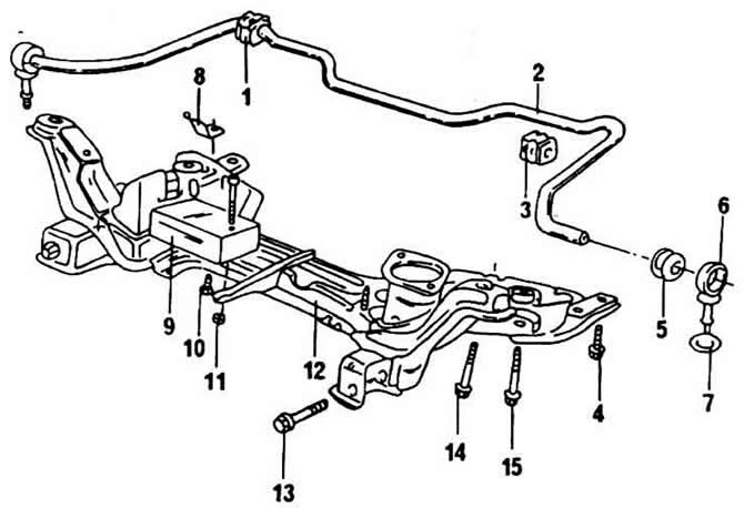
Removal and installation of the anti-roll bar
1 - rubber support bushing on the subframe
2 - anti-roll bar
3 - rubber support bushing on the subframe
4 - screw, 65 Nm
5 - rubber support at the end of the stabilizer
6 - connecting rod
7 - shaped washer, conical side facing the transverse lever
8 - mounting bracket
9 - vibration damper
10 - screw, 25 Nm
11 - nut, 25 Nm
12 - subframe
13 - screw M12x83, 50 Nm, then turn again by 90°
14 - screw M12x65, 70 Nm, then turn another 90°
15 - screw M12x78, 70 Nm, then turn another 90°
On the outside, the stabilizer is attached to the underside of the car using brackets and rubber supports and is connected to the transverse arms using a connecting rod. The connecting rod is attached to the underside of the transverse arm using a nut. The sheet metal disk is installed under and above the transverse arm using a rubber support. When dismantling, it is necessary to pay attention to the exact order of the arrangement of the mentioned parts. The conical surface of the rubber bushings is facing the sheet metal disk, while the sheet metal disks with their flanged edges are turned in the opposite direction from the bushings.
Visitor comments