



Remove the wheel nuts and place the rear of the car on jack stands.
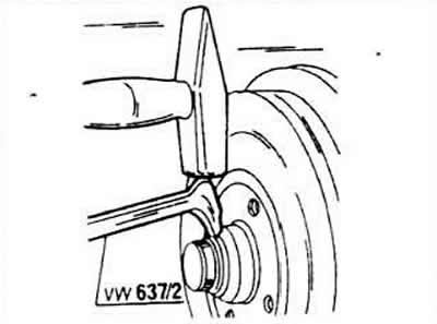
Remove the wheel and cap. The instructions call for a special tool, but the cap can be carefully removed with a screwdriver (alternately shifting left and right).
Remove the cotter pin from the nut lock and remove the locking device.
Unscrew the adjusting nut and remove the washer.
For drum brake versions, remove the brake drum. This will release the outer bearing.
For versions with disc brakes, remove the brake saddle (without opening the device) and remove the brake disc together with the hub. This will release the outer bearing.
The further disassembly process proceeds depending on the design option.
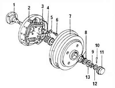
Cars with drum brakes
1 - end of the axis
2 - brake support plate
3 - oil seal ring
4 - inner wheel bearing
5 - shaped washer
6 - screw, 60 Nm
7 - brake drum
8 - outer wheel bearing
9 - hex nut
10 - cotter pin, always replaceable
11 - hub cap
12 - nut lock
13 - thrust washer
Place the brake drum on an open vice, insert a mandrel from the front and knock out the rear bearing and grease sealing ring. Knock out both working bearing rings from the drums from opposite sides.
Drive in new rings and lubricate the new bearing with grease.
Insert the inner bearing and carefully tap the sealing ring in thoroughly. Wipe off any grease that has squeezed out onto the surface.
The brake drum can now be reinstalled. These operations are not performed on vehicles with built-in anti-lock braking system.
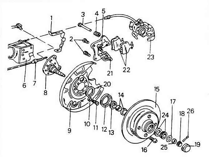
Cars with disc brakes
1 - handbrake cable mount
2 - screws, 65 Nm
3 - guide bolt, brake seat
4 - protective cuff
5 - self-locking screw, 35 Nm
6 - spring clamp
7 - handbrake cable
8 - end of the axis
9 - mudguard
10 - shaped washer, convex side facing the mudguard
11 - screw, 60 Nm
12 - anti-lock braking device ring gear
13 - grease sealing ring
14 - inner wheel bearing
15 - wheels
16 - wheel screw, 110 Nm
17 - thrust washer
18 - nut lock
19 - hub cap
20 - bearing cap
21 - Brake seat support
22 - brake pad set
23 - brake saddle
24 - outer bearing ring
25 - bearing adjusting nut
26 - cotter pin
Clamp the brake disc in a vice with metal or aluminum jaws and use a screwdriver to knock out the metal cap on the inside of the drum.
[The information is presented on the website: VWmanual.ru]
Place the brake disc with the inner side on the open jaws of the vice, insert the mandrel from the front and knock out the inner bearing together with the grease sealing ring. Knock out both working rings from the drum from opposite sides.
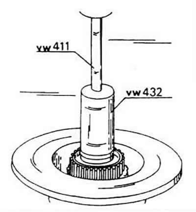
Clean both ends thoroughly.
Assemble new bearings as described for the version with drum brakes, but place the brake disc together with the wheel hub on the open vice to drive in the outer ring of the inner wheel bearing. As can be seen from the figure, the anti-lock device crown is on the brake disc, which must not be damaged. Insert a section of pipe along the outer circumference of the bearing. After this, turn the brake disc (hub) over and similarly drive in the outer ring of the wheel bearing. In this case, do not push the wheel hub onto the surface of the drum, but compact it well from below, then a reliable stop will be provided when driving in.
Grease the wheel bearings well with grease, insert them from the back of the wheel hub and, being careful, drive the grease seal ring from the side shown in the picture until it is securely seated. Again, check whether the crown has been damaged during this operation.
Drive a tin cap with a mandrel of a suitable diameter into the inside of the wheel hub without crushing it. It is necessary to ensure that when replacing the wheel bearings, the toothed ring intended for indicating the speed, i.e. the number of revolutions of the rear wheel, related to the anti-lock device, is not damaged.
Move the brake disc towards the end of the axle.
Mount all parts on the outside of the wheel hub.
Re-adjust the bearing clearance.
Tighten the nut tightly while the drum or brake disc rotates in different directions. This is necessary to insert the bearings into the working rings. Then loosen the nut again.
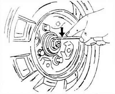
Tighten the nut again until the working end of the screwdriver can still move the disk under the nut from side to side.
In this position, insert the nut lock and place a new cotter pin in it. If the cotter pin does not fit, you can tighten the nut a little, but remember that after this operation the disc must be able to move freely.
Visitor comments