
Through the hole in the left wall of the crankcase, insert the locking pin 4 and insert the rod 4 (pic. 300) I / II gears simultaneously with the installation of the input shaft.
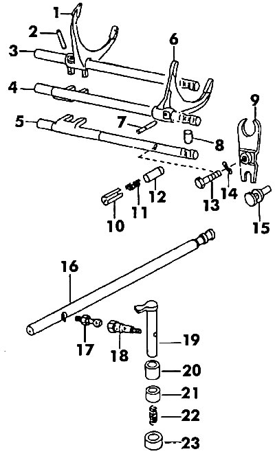
Pic. 300. Gear selection mechanism (inside the gearbox): 1 - forks III / IV gears; 2, 7 - pins; 3 - a rod of inclusion of III/IV transfers; 4 - stock I / II gears; 5 - stock; 6 - forks of I / II gears; 8 - latch; 9 - reverse gear lever; 10 - bushing; 11 - spring; 12 - guide sleeve; 13 - bolt M10x32; 14 - spring washer; 15 - emphasis; 16 - gear selection rod; 17, 18 - bolts; 19 - wings; 20, 21 - bushings; 22 - spring; 23 - casing
In the hole on the right side of the crankcase, enter the rod of 3rd / 4th gear simultaneously with the input shaft. Locking pin 4 (see fig. 283) must be between the rods of I/II gear and III/IV gear.
Insert the second locking pin.
Insert the reverse rod into the next left hole.
Insert the parts of the spring locks of the rods into the holes in the sequence shown on rice. 283. Screw on the screw plugs with gaskets, as well as the plug of the locking pins on the side. The rod blocking device is shown in fig. 301.
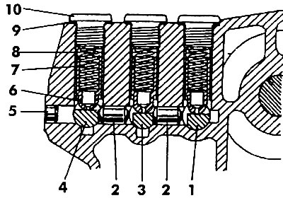
Pic. 301. The device for blocking the rods of the gear selection mechanism: 1 - stem III/IV gear; 2 - blocking pin; 3 - rod I / II transmission; 4 - reverse rod; 5 - plug; 6, 8 - bushings; 7 - spring; 9 - gasket; 10 - screw plug
After placement and installation of the main gear (see description below) you can start connecting both parts of the gearbox housing (pic. 302, 303). These operations are performed in the reverse order of disassembly. If the clutch side of the crankcase has been replaced, adjust the bearing preload.
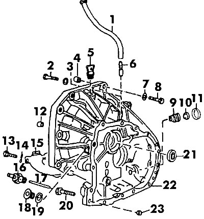
Pic. 302. Part of the gearbox housing from the clutch side: 1 - air tube; 2 - bolt; 3 - washer; 4 - guide sleeve; 5 - screw plug; 6 - air tube fitting; 7 - washer; 8 - bolt M12x68; 9 - bushing; 10 - gasket; 11 - gasket ring; 12 - guide sleeve; 13 - bolt; 14 - spring ring; 15 - shield; 16 - switch; 17 - pusher; 18 - drain plug; 19 - gasket; 20 - bolt M8x45; 21 - stuffing box; 22 - gearbox housing from the I side of the clutch; 23 - sleeve
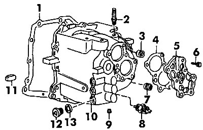
Pic. 303. The second part of the gearbox housing: 1 - gasket; 2 - double-sided bolt with a flange; 3 - screw plug; 4 - cover gasket; 5 - gearbox cover; 6 - bolt; 7 - screw plug; 8 - switch; 9 - plug: 10 - crankcase; 11 - magnet; 12 - oil drain plug; 13 - gasket
The mating surfaces of both parts of the crankcase must be coated with sealant before joining (e.g. D3). Before tightening the bolts, install the pins. Insert both drive shafts into the splines of the differential gears and finish them off with a rubber mallet. The right shaft is longer and must be installed from the clutch housing side. holding flange (see fig. 279), tighten the bolts to 25 Nm.
Replaced bolts must match the old ones, even if the flange has been replaced.
Visitor comments