
The input shaft needle bearing is removed after dismantling the clutch release bearing and oil seal. The new bearing is installed with the lettering facing out.
A puller is required to remove the needle bearing of the axle drive shaft (Kukko 21/5). The new bearing is pressed flush with the gearbox housing.
The inscription on the bearing must point towards the tool. On fig. 281 shows the gearbox housing from the clutch side and the location of both bearings. Repair of the second part of the housing can only be carried out after the input and drive shafts are removed (see here). Don't lose the magnet placed on the case (arrow in fig. 281).
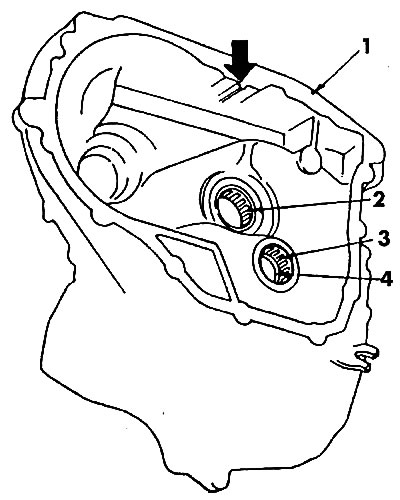
Pic. 281. Transmission housing from the clutch side: 1 - gearbox housing; 2 - needle bearing of the shaft with half shaft water; 3 - needle bearing of the input shaft; 4 - sealing ring; the arrow indicates the protrusion that fixes the position of the magnet
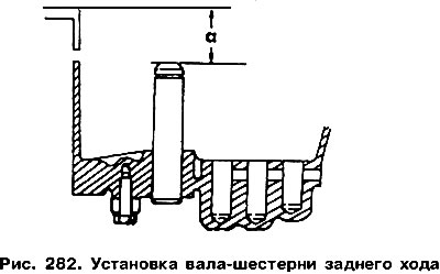
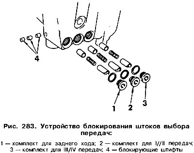
Remove the sealing ring, remove the bearing race with a puller (Rullex 6304). Plugs are installed in the crankcase for draining and filling oil, as well as a reversing light switch. When installing these parts, tighten them with the following torques: 25 Nm - oil drain and fill plugs, 30 Nm - reversing light switch. If the reverse gear shaft was replaced, which happens extremely rarely, then during its installation it is necessary to pay attention to the fact that the distance «A» (pic. 282) from the end of the shaft to the edge of the crankcase was 83.3 mm. During the installation of the shaft, it is necessary to heat (small flame) the edges of its hole, and grease the shaft itself with AMV 185 10001. In fig. 283 shows the placement of the rod blocking device, which prevents the simultaneous inclusion of two gears. The installation method of this device will be described in the paragraph «Gearbox Assembly».
The dismantling of the input shaft can be done without removing the output shaft. Why separate both parts of the gearbox housing (see here). On the side of the crankcase, unscrew the three screw plugs (see fig. 283) and remove the parts underneath.
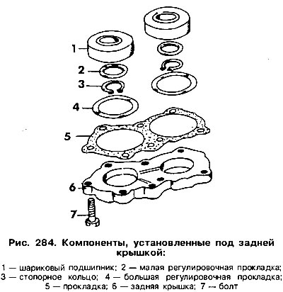
Remove the cover from the rear wall of the crankcase and remove the shims (pic. 284). Gaskets cannot be interchanged, and therefore it is recommended to attach tags to them with the designation of the shaft (splined shaft is primary).
Replace carton. From inside the crankcase, remove the shift control lever and remove the reverse gear engagement rod and control lever pin.
In the place indicated by the arrow in Fig. 285, carefully install the M16 nut to lock the shift shaft,
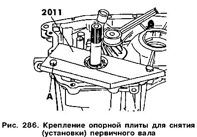
Above the input shaft install the base plate 2011 (pic. 286) and bolt it to the crankcase. If you do not have this plate, then it can be replaced with a metal plate with holes.
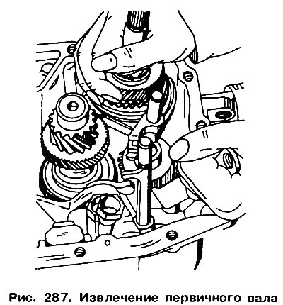
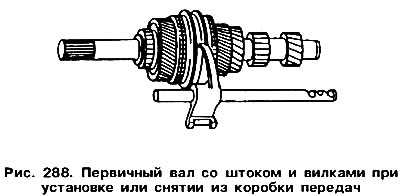
From the other end of the input shaft, remove the circlip and small shim. Remove the bearing with a puller (Rullex 6304), remove the plate and take out the input shaft with the III / IV gear rod (pic. 287). In this case, you should raise the reverse gear with a hook (as shown in the right corner of Fig. 287), to release the gear teeth. On fig. 288 shows parts that should be removed at the same time.
The output shaft can only be dismantled after the input shaft has been removed. The output shaft is removed along with the 1/11 gear rod and reverse gear.
Remove the input shaft in the manner described above.
From the toe of the output shaft, remove the circlip and the small bearing shim. Remove the bearing from the crankcase (Requires puller Rullex 6304)
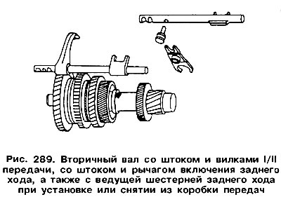
Remove the secondary shaft and rod with forks and remove together with the reverse gear (pic. 289).
Visitor comments