



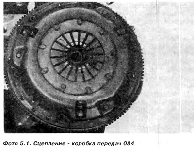
2. Mark the relative positions of the clutch and flywheel (photo 5.1).
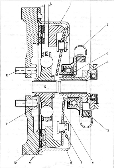
Figure 5.1. Clutch operation diagram - (solution applied until 1985.)
1 - pressure ring; 2 - spring ring; 3 - clutch release bearing; 4 - guide bushing; 5 switch forks and disc spring; 7 - fastening rivet; 8 - clutch pressure housing; 9 - friction linings 10 - flywheel; 11 - Clutch disc; 12 - clutch shaft; 12 - bolts securing the flywheel.
3. Using a hex key, first loosen and then remove the bolts securing the clutch release to the flywheel. If necessary, lock the flywheel using a screwdriver inserted between the teeth of the flywheel ring gear.
4. Remove the clutch pressure plate and the clutch disc from the flywheel. The clutch disc hub, which closes the springs of the vibration damper during turns (rotations), faces the clutch pressure plate.
5. Check the clutch elements.
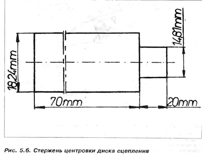
6. Before assembly, it is necessary to find a tool for centering the clutch disc. If the disc is not centered, problems will arise when assembling the gearbox. Unlike typical solutions, the clutch shaft of the gearbox is not located at the rear of the crankshaft. If the clutch disc is not centered, problems will arise when installing the clutch cover on the retaining studs. If a centering tool is not available, a rod with the dimensions given in Figure 5.6 can be used.
Assembly
7. Clean the rubbing surfaces of the flywheel and pressure ring, then secure the centering tool in the crankshaft journal and place the clutch disc on it.
8. Install the clutch pressure on the flywheel (paying attention to the markings made during disassembly), then insert the bolts and tighten them evenly crosswise to a certain torque
9. Before assembling the gearbox, check the release bearing as described in point 7.
Visitor comments