
English Русский
Български
Беларускі
Український
Српски
Hrvatski
Română
Polski
Slovenský
Magyar
  |  Articles  |  Sitemap  |  Contacts  |    |
Car maintenance Ford Car maintenance Hyundai Car maintenance Chevrolet Car maintenance BMW Car maintenance Audi Car maintenance Opel Car maintenance AvtoVAZ
VWmanual.ru


Main   Passat   Golf   Polo   Touareg   Tiguan   Sharan   Transporter   Others  
Golf 1 (1974-1984, diesel) Golf 1 (1974-1984, petrol) Golf 2 (1984-1993, petrol) Golf 2 (1984-1993) Golf 3 (1991-1997) Golf 4 (1997-2004) Golf 5 (2003-2008)

Clutch device (VW Golf 2)

  • Main
  • Golf
  • Golf 2
  • Transmission
  • Clutch
  • Clutch device
            0


Clutch assembly (figure 5.1) consists of:

a) flywheel 10;
b) clutch disc 11;
c) clutch compression;
d) clutch release bearing 3;
d) guide sleeve and release bearing;
e) forks disengaging the clutch with lever 5;
g) clutch cable;
c) clutch pedals.
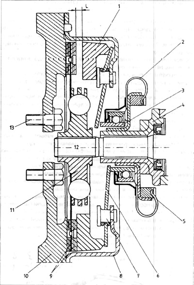
Figure 5.1. Clutch operation diagram - (solution applied until 1985.)

1 - pressure ring; 2 - spring ring; 3 - clutch release bearing; 4 - guide bushing; 5 switch forks and disc spring; 7 - fastening rivet; 8 - clutch pressure housing; 9 - friction linings 10 - flywheel; 11 - Clutch disc; 12 - clutch shaft; 12 - bolts securing the flywheel.


The main element of the clutch assembly is the clutch disk. It transfers the drive from the engine flywheel to the clutch shaft of the gearbox. The clutch disk consists of a hub with an internal spline, a rotary shock absorber and friction linings. The hub is connected to the linings by means of a rotary shock absorber and springs that cushion sharp impacts of the torque.

The oscillation shock absorber consists of friction rings, which, moving relative to each other, dampen the vibrations of the shock absorbing springs. The remaining elements serve to smoothly connect the engine to the gearbox in order to transmit the drive to the wheels of the car. The next solutions of the clutch assembly provide greater reliability and convenience in controlling this assembly.


VW vehicles use two clutch design solutions. These two solutions use a disc spring as an actuator. The disc spring has the best characteristics, which results in the force produced by the clutch pedal stroke being significantly lower. This results in a higher comfort of clutch control with the same torque transferred through the clutch. The first solution mentioned is the typical system shown in the figure (figure 5.1)

When the clutch pedal is released, the disc spring 6 presses the clutch disc 11 onto the flywheel via the pressure ring 1. This is shown in the lower part of Figure 5.1. The torque is transferred from the flywheel via the friction linings 9 and the clutch disc to the clutch shaft 12 of the gearbox. When the driver presses the clutch pedal, the release bearing 3 will be pushed along the sleeve 4 by the release forks.

The position of the release bearing after pressing the clutch pedal is visible in the upper part of Figure 5.1.

When the release bearing moves toward the disc spring, the inner part of the disc spring bends. Since the spring disc is attached to the clutch pressure housing 8 with rivets 7, after the inner part of the spring bends, its outer part bends in the opposite direction, pulling out the pressure ring 1. After the pressure ring is pulled, the flywheel rotates freely, without transmitting torque to the clutch shaft. The second solution, shown in the figure, includes similar elements located slightly differently (figure 5.2).
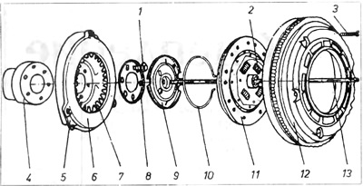
Figure 5.2. Clutch elements

1 - bolt securing the clutch clamp; 2 - springs of the shock absorber when turning; 3 - flywheel securing bolt; 4 crankshaft journal; 5 - clutch compression; 6 - pressure ring, 7 - disc spring; 8 - washer; 9 - switch-off disk; 10 - spring ring; 11 - Clutch disc; 12 - flywheel; 13 - clutch pusher.


Clutch pressure 5 is screwed to crankshaft journal 4 using bolts 1 and washer 8. Flywheel 12 is attached to clutch pressure housing 5. In this system, the flywheel is screwed to the crankshaft journal, and the pressure housing is screwed to the flywheel.


The second fundamental difference is the use of a pusher located in a groove in the clutch shaft.

The release bearing and the release forks are located in the rear gearbox housing. After pressing the clutch pedal 5, the clutch cable 1 rotates the clutch lever (figure 5.4)
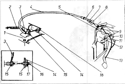
Figure 5.4. External Clutch Release System - 084

1 - gearbox housing; 2 - tension spring; 3 - switch-off lever; 4 - clutch cable; 5 - clutch pedal shoulder; 6 - end of metal cable protection; 7 - locking washer; 8 - pass; 9 - pedal travel limiters; 10 - pedal kingpin housing; 11 - pre-storage of kingpin; 12 - engine bulkhead; 13 clutch pedal; 14 - cable bracket; 15 - centering sleeve; 16 - lock nut; 17 - adjusting nut; 18 - place for adjusting the cable length.


On the lever axis inside the gearbox there is a shoulder that moves the release bearing. The release bearing presses through the pusher 13 on the release disk (figure 5.2).

The release disk bends the disk spring, which, similar to the first solution, pulls back the pressure ring 6 and releases the clutch disk. The drive transmission is interrupted. The release disk is attached to the disk spring by means of the spring ring 10.

[The original text is available on the website: VWmanual]

This article is available at russian, bulgarian, belarusian, ukrainian, serbian, croatian, romanian, polish, slovak, hungarian
The text has been checked: Semenova Anna

Share information:

Previous articles
Technical data
Next articles
Clutch — adjustment
Clutch cable — replacement
Clutch pedal — disassembly and assembly
Clutch — Gearbox 084
Clutch — 084 control
Clutch Release Mechanism — 084


Similar articles from other manuals for VW cars:
Clutch device Passat B3 (1988-1993)
Device switches Polo 3 (1995-2003)
Fuel tank device Tiguan 1 (2007-2015)
Clutch — design description Sharan 1 (1995-2000)
Windscreen wiper drive device Transporter T4 (1990-2003)
A device that prevents children from opening a sliding door Caddy 3 (2003-2010)
Link to this page in different formats


Visitor comments


No comments yet


How much will 25 + 15 =


Golf 5 
  • General information
  • User manual
  • Maintenance
  • Troubleshooting
  • Power unit
  • Engine repair
  • Cooling and ventilation system
  • Fuel system
  • Ignition system
  • Transmission
  • Clutch
  • Mechanical gearbox
  • Automatic gearbox
  • Chassis
  • Brake system
  • Car suspension
  • Steering
  • Body
  • Interior (internal elements)
  • Exterior (external elements)
  • Doors and covers
  • Electrical equipment
  • Power devices
  • Washers and wipers
  • Lighting and appliances
  • Electrical circuits
Golf 4 
  • General information
  • User manual
  • Weekly checks
  • Maintenance
  • Power unit
  • Petrol engines
  • Diesel engines
  • Cooling system
  • Fuel system (petrol)
  • Control system (petrol)
  • Fuel system (diesel)
  • Exhaust system
  • Transmission
  • Clutch
  • Car gearbox
  • Drive shafts
  • Chassis
  • Car suspension
  • Steering
  • Wheels and tires
  • Brake system
  • Body
  • Exterior (external elements)
  • Interior (internal elements)
  • Ventilation and heating
  • Car doors and sunroof
  • Washers and glass cleaners
  • Electrical equipment
  • Power devices
  • Lighting and appliances
  • Electrical circuits
Golf 3 
  • Petrol engine
  • Engine repair
  • Lubrication system
  • Cooling system
  • Ignition system
  • Diesel engine
  • Engine repair
  • Diesel injection system
  • Pre-glow system
  • Transmission
  • Clutch
  • Gearbox and drive shafts
  • Chassis
  • Steering
  • Wheels and suspension
  • Brake system
  • Electrical equipment
  • Lighting and appliances
  • Electrical circuits
Golf 2 
  • General information
  • Introduction to guide
  • User manual
  • Petrol engines 1.3 l
  • Engine repair
  • Lubrication system
  • Cooling system
  • Carburetors
  • Supply system
  • Ignition system
  • Petrol engines 1.6/1.8 l
  • Engine repair
  • Supply system
  • Ignition system
  • Diesel engines
  • Engine repair
  • Lubrication system
  • Cooling system
  • Power and exhaust system
  • Transmission
  • Clutch
  • 4-speed gearbox 084
  • 5-speed gearbox 085
  • 4-speed gearbox 020/4R
  • 5-speed gearbox 020/4T
  • Automatic gearbox
  • Drive shafts
  • Chassis
  • Steering
  • Car suspension
  • Brake system
  • Body
  • Body elements
  • Doors, locks and windows
  • Electrical equipment
  • Equipment and devices
  • Power devices
Golf 2 (petrol) 
  • General information
  • Characteristics
  • Car care
  • Maintenance
  • Power unit
  • Engine repair
  • Engine 1.05/1.30
  • Engine 1.60/1.80
  • Cooling and lubrication system
  • Power and exhaust system
  • Transmission
  • Clutch
  • Car gearbox
  • Drive shafts
  • Chassis
  • Brake system
  • Steering
  • Suspension
  • Body
  • Body and equipment
  • Electrical equipment
  • Lighting and appliances
  • Electrical circuits
Golf 1 (petrol) 
  • General information
  • Characteristics
  • User manual
  • Maintenance
  • Power unit
  • Engine adjustment
  • Engine 1.1/1.3
  • Engine 1.5/1.6/1.8
  • Engine electrical equipment
  • Cooling system
  • Fuel system
  • Transmission
  • Clutch and manual gearbox
  • Automatic gearbox
  • Chassis
  • Steering
  • Front suspension
  • Rear suspension
  • Brake system
  • Electrical equipment
  • Lighting and appliances
  • Electrical circuits
  • Body
  • Body and equipment
  • Optional equipment
Golf 1 (diesel) 
  • General information
  • Specifications
  • Maintenance
  • Power unit
  • Engine repair
  • Exhaust and turbocharger
  • Cooling system
  • Fuel system
  • Fuel injection system
  • Transmission
  • Clutch and drive shafts
  • Car gearbox
  • Chassis
  • Suspension and wheels
  • Steering
  • Brake system
  • Wheels and tires
  • Body
  • Heating and ventilation
  • Exterior (external elements)
  • Interior (internal elements)
  • Doors and windows
  • Electrical equipment
  • Equipment and devices
  • Lighting system
  • Power devices
  • Electrical circuits
VWmanual.ru © 2016-2026 | Mobile version | News and articles | Sitemap: EN BG BY UA RS HR RO PL SK HU | Write message | Site search
Passat B2 • Passat B3 • Passat B4 • Passat B5 • Passat B6 • Golf 1, diesel • Golf 1, petrol • Golf 2, petrol • Golf 2 • Golf 3 • Golf 4 • Golf 5 • Polo 3 • Polo 4 • Touareg 1 • Tiguan 1 • Sharan 1 • Transporter T3 • Transporter T4 • LT 28 • LT 2D • Beetle • Caddy 3 •
Our website uses cookies to ensure functionality and convenience.