



Contents: Vane pump ↓ Distributor piston and thrust washer ↓ Electromagnetic switch ↓ Centrifugal governor ↓ Injection advance regulator ↓ Cold start accelerator ↓ Fuel supply regulator ↓
Vane pump
The first link of the fuel distribution pump is the vane pump. It sucks fuel from the pipeline that comes from the filter. The pump rotor, in which movable, sliding plates are installed, is placed in a stator of a special shape. The sliding plates always adhere to the stator walls, since the rotor rotates during engine operation, and under the action of centrifugal force and fuel pressure, they tend to leave the rotor grooves. This is how sealing is achieved. When the rotor rotates, the cavity between the rotor, plates and stator decreases toward the discharge side of the pump, compressing the fuel.
Distributor piston and thrust washer
Thus, the fuel under pressure moves in the fuel pump body. There is a distribution piston. It is the most important part of the pump.
The principle of operation of the distributor piston is similar to the principle of operation of the ignition distributor of a carburetor engine. The distributor piston is pierced with holes and has grooves. During injection, the piston's distribution window is located opposite the inlet port. Fuel supplied by a vane pump under pressure enters the injector through channels in the piston, while the piston moves forward (more on that below) and the fuel is compressed even more, injection occurs.
The distributor piston rotates further. The inlet port closes again. Injection stops.
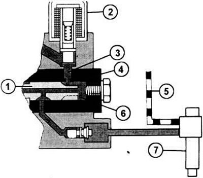
By turning the distributor piston (1), the inlet opening (3) coincides with the distributor window (4) - a recess in the piston. The fuel supplied under pressure from the vane pump now enters the so-called high-pressure cavity (6) and fills the cavity completely. This completes the filling. The remaining numbers indicate: 2 - switch; 5 - drain pipe to the tank; 7 - nozzle.
Now we will talk about the other two parts. The distributor piston is connected to a washer, which has four thickenings in the form of projections. This is a pushing washer, which moves near a counter-support, which has four rollers to reduce friction. The rollers are located at the same distances from each other as the projections on the washer.
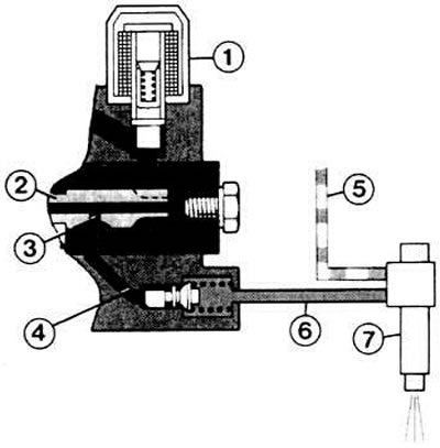
After filling is complete, the distributor piston (2) rotates further. Now the inlet is closed by the piston. In the fuel pump, the projections of the pusher washer run onto the ring rollers. Therefore, the piston, rigidly connected to the pusher washer, moves forward. The pressure in the high-pressure chamber increases above the level that is usually in the fuel pump. At this point, channel (3), due to the rotation of the piston, is in such a position that its opening coincides with the opening of the outlet channel (4). Now, through the high-pressure fuel line (6), the fuel under high pressure moves to the injector (7). which carries out the injection. The rest of the fuel flows back to the tank through the drain pipe (5). Of course, the switch (1) must open the access of fuel to the high-pressure chamber.
And again about injection. The pusher washer moves near the roller ring. When the projections are pressed onto the rollers, the pusher washer moves forward together with the distributor piston. This happens exactly at the moment when the hole in the piston coincides with the channel that leads to the injector. Consequently, fuel can be supplied to the side of the cylinder where compression occurs. Due to the forward movement of the distributor piston, the volume of the cavity in front of it decreases. The fuel, already under pressure, is additionally compressed and squeezed out to the injector.
The crankshaft continues to turn, the high-pressure fuel pump operates. The distributor piston slides back. Additional fuel comes from the inlet. The distributor piston turns toward the outlet of the next cylinder. The projections of the pusher washer roll onto the ring rollers again. The distributor piston moves forward, fuel is injected under pressure into the next cylinder.
[The information is posted on this website vwmanual.ru]
Electromagnetic switch
Before the diesel fuel reaches the inlet at the distributor piston, it flows past the electromagnetic valve-switch. When the ignition key is turned to the first position, voltage is supplied to the electromagnetic switch and the path for the fuel opens. When the engine is turned off, the key interrupts the electrical circuit. Then the switch closes the inlet, the engine stops. There is no other way to stop the diesel engine (except: close the air filter tube or outlet pipe).
A car with an automatic transmission also has a mechanical switch at the front of the pump. This switch can be used to stop the engine if the electromagnetic switch is faulty.
Centrifugal governor
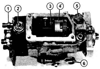
The illustration shows a Bosch fuel pump in an open position (it is not recommended to open it yourself); the centrifugal regulator (4) with its counterweights and (3) is clearly visible; further you can see: 1 - threaded fitting for the fuel line to the injector; 2 - switch; 5 - hollow bolt of the fuel supply line; 6 - cold start accelerator lever.
The high-pressure fuel pump has a centrifugal regulator to regulate the amount of fuel injected at different engine operating modes. The centrifugal regulator counterweights open more or less depending on the engine speed and move the pusher. The counterweights press the regulating valve via a lever mechanism, which allows excess fuel to flow out. To do this, the valve opens a hole in the distribution piston.
If the engine speed is too high for a particular accelerator pedal position, the regulator opens a hole in the distributor piston and the speed decreases.
When starting, the control hole is completely closed. The engine receives the full amount of fuel, but only until the idle speed is reached.
The same thing happens at idle and partial load. The centrifugal governor "matches" the accelerator pedal position and the engine speed by means of a mechanical system. When a certain speed is reached according to the pedal position, the governor stops working. The maximum engine speed is also limited by the centrifugal governor.
The control hole opens if the engine speed exceeds the following values:
- 5550±50 min (for 1.5 l)
- 5350±50 min (for 1.6 l)
- 5100±50 min (for turbodiesel engine)
Injection advance regulator
As the engine speed increases, the fuel must be injected earlier to ensure mixture formation. The injection advance controller performs this task: it regulates the injection moment depending on the position of the piston in the cylinder.
When the engine speed increases, the vane pump in the injection pump rotates faster. Therefore, the fuel pressure increases. This phenomenon is used in the operation of the regulator. Fuel under pressure acts on the piston of the regulator, shifts it, overcoming the force of the spring. The roller ring is rigidly connected to this piston. The illustration on shows this. With increasing fuel pressure (that is, at a higher number of revolutions) the piston rotates the roller ring slightly around its axis. Therefore, the projections of the pusher washer run onto the rollers earlier; thus, the injection occurs earlier. As the number of revolutions decreases, the piston and the roller ring return back, the injection advance decreases.
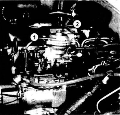
The regulator diaphragm (1) is located at the top of the fuel pump and is connected to the intake manifold via an air hose (2). If the boost pressure increases as a result of the turbocharger operation, the diaphragm bends, increasing the fuel supply
Cold start accelerator
Sometimes the cold start accelerator button (on the left side of the steering wheel) is compared to the "Choke" button of some carburetor engines. But the two buttons have little in common. The button also extends when the engine is cold, but the air flow does not decrease because of this, but the injection moment shifts, it is carried out earlier. Then the cold engine starts better, since the fuel is injected earlier and has more time to mix with the cold air. In addition, the engine then picks up speed better in the first phase of a cold start.
Annoying blue smoke from the exhaust pipe (which, when started, gives rise to the suspicion that the engine is badly damaged) almost absent when the cold start accelerator button is pulled out.
The cold start accelerator button should be pulled out completely when starting off with a cold engine, regardless of the outside temperature. After driving for about 1 minute, it should be pushed back in again. If you forget to push it back in once, it is not a big deal. The engine then runs a little harder and does not develop full power. What does the cold start accelerator do in the high-pressure fuel pump? The answer is very simple. It performs the same function as the injection advance regulator (read in the previous section) The cold start accelerator rod acts through the lever on the governor piston and pushes it back (how is the fuel pressure at high rpm). This causes the roller ring to rotate approximately 2.5 degrees for earlier injection.
Fuel supply regulator
An additional device is located on top of the high-pressure fuel pump (in a car with a turbodiesel).
This is a fuel supply regulator. It performs the following function. The excess air that was forced in by the turbocharger requires additional fuel depending on the existing boost pressure. The device works as follows.
The membrane located at the top of the housing is subjected to the boost pressure from the suction pipe through a hose. This causes the membrane to bend downwards and transmit this movement through the pusher and the angle to the same regulating valve, which is also affected by the centrifugal regulator. If the boost pressure increases, the valve closes the opening of the distribution piston longer than usual. Consequently, the excess fuel cannot evaporate, but is injected. Thus, with increased boost pressure, more fuel is supplied.
Visitor comments