
Engine block
The diesel engine block is cast in gray cast iron. Below is the crankshaft, above are the cylinders (four in one row). They are surrounded by coolant channels.
Crankshaft
The up and down movement of the piston is converted into rotary motion by the crankshaft. Four connecting rods connect the crankshaft to the pistons. The crankshaft is mounted in a block on five bearings. To reduce friction in the bearings and the lower heads of the connecting rods, plain bearings are installed, which are replaceable semicircular liners. To balance the inertial moments that occur during engine operation, the crankshaft has counterweights.
Pistons
For the diesel engine, the so-called autothermal pistons of the company "MALE" (Stuttgart). The peculiarity of these pistons is that they have a special shape. In the upper third of the piston there are three piston rings in corresponding grooves. The upper piston ring, which has a rectangular section, is located in an annular insert, which is cast from a special alloy. In this way, it is possible to prevent high wear of the upper annular groove, since this place bears the maximum load.
The two upper rings are compression, perceiving the pressure of gases. The bottom ring is oil scraper.
Cylinders
As already mentioned, the cylinders are part of the engine block. The surfaces of the cylinders are smoothly ground (honed), since they are sliding surfaces for pistons. The dimensions of the cylinder bores correspond to the diameters of the pistons. When overhauling engines, the holes are ground a few tenths of a millimeter more in order to remove wear marks and insert repair pistons. They come in three sizes.
Cylinder head gasket
The gasket has the following purpose: high pressures in the combustion chambers must not affect the channels with oil and cooling water. For diesel engine "Volkswagen" cylinder head gaskets of various thicknesses are installed. It depends on which group the liner-piston mate is assembled, according to the upper or lower tolerance. As you know, the cylinder head gasket is located between the cylinder block and the cylinder head. By choosing an appropriate gasket thickness, it is possible to vary the height of the combustion chamber and thus compensate for the difference in height between different groups of pistons.
Cylinder head and camshaft
At the top, in the cylinder head, is the camshaft. With his oval cams, he presses the valves, and they open and close at certain positions of the pistons. Therefore, the shaft determines the so-called distribution moments.
Due to the special mounting arrangement of the camshaft, the movement of the valves is controlled by the shortest transmission path: the camshaft eccentrics press on the intermediate bearings (cup pushers), which then push down on the valves against the force of the valve springs. Thus the valve opens. The cams are not in contact with the pushers exactly in the middle, but with a slight offset. Thanks to this, the valves rotate around their own axis with each downward pressure. This prevents uneven wear and leakage that occurs over time. For better heat dissipation, the exhaust valves are located on the outside of the engine. Swirl chambers are also inserted into the cylinder head along with nozzles and glow plugs.
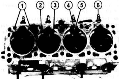
Dismantled cylinder head, bottom view: 1 - channels with coolant; 2 - one of the exhaust valves; 3 - one of the inlet valves; 4 - vortex chamber insert; 5 - channel opening; 6 - glow plug.
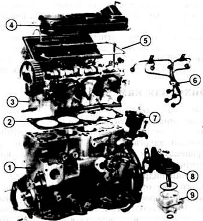
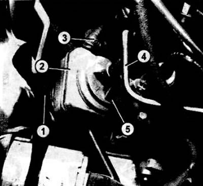
Disassembled diesel engine: 1 - engine block; 2 - cylinder head gasket; 3 - cylinder head; 4 - valve cover; 5 - valve cover seal; 6 - high pressure fuel lines; 7 - brake booster vacuum pump; 8 - oil pump flange: 9 - oil pump.
Toothed belt
The camshaft is driven from the crankshaft by a toothed belt. In a diesel engine, the timing belt is of great importance. When the toothed belt breaks, the rotation of the camshaft, coordinated with the rotation of the crankshaft, stops. Some valves remain open and are hit by a moving piston. As a result, the valve is deformed, the piston cracks, the connecting rod may break, etc.
This case, of course, is prevented by certain constructive techniques. Such techniques are as follows: placement of the entire belt drive in a protective casing, installation of a toothed belt pulley; on the key, it is necessary to maintain a certain angle of coverage of the toothed belt at the crankshaft pulley. This angle should be 215 degrees.
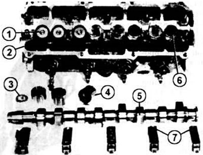
The illustration shows the camshaft (5), five caps unscrewed (7) bearings; shaft removed from cylinder head (2). Cup pushers shown assembled (6) and disassembled (4). The cup pusher is mounted as an inverted cup on the stem and valve head (1). Adjustable washers are inserted into the cup pushers from above (3).
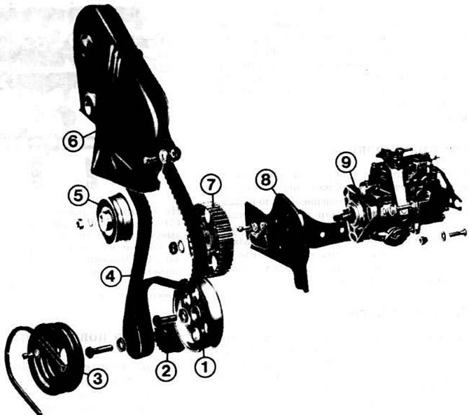
The illustration shows the location of the toothed belt (4): 1 - intermediate shaft drive pulley; 2 - a pulley of a gear belt of a cranked shaft; 3 - crankshaft V-belt pulley; 5 - tension roller; 6 - toothed belt casing; 7 - toothed belt pulley, injection pump; 8 - fuel pump bracket; 9 - high pressure fuel pump.
Lubrication system
The oil needed to lubricate the engine is supplied from the crankcase by the oil pump through the intake pipe and filter. Under pressure, the oil passes through the oil filter to the crankshaft lubrication points, pistons, intermediate and camshafts. Once lubricated, the oil flows back into the crankcase where it can cool slightly before passing through the engine again.
Oil pump
Like carbureted engines, diesel engines have a gear oil pump, which has two small but wide gears that constantly mesh. Together they direct oil from the suction to the discharge side of the pump.
The oil pump, together with its intake pipe, is installed below, in the crankcase. It is driven by an intermediate shaft through a toothed belt.
Oil pump relief valve
To prevent the oil pressure in the lubrication system from becoming too high, there is a safety valve in the pipeline from the oil pump to the oil filter, which, if necessary, opens and allows excess oil to flow back to the suction side of the pump.
Oil radiator
An oil cooler is located between the oil filter and the filter flange on a machine with an automatic transmission or turbo engine. The flowing oil is not cooled by air, but by the coolant.
Between oil filter (1) and flange (5) oil filter, a car with a turbo engine or automatic transmission has an oil cooler (2). It is flushed with coolant, which also cools the oil. Position "3" indicates the connection of the coolant hose. A pipeline also branches off directly from the oil cooler (4) (With butter), leading to the turbocharger.
Crankcase ventilation
Engine crankcase ventilation eliminates excess pressure inside the engine. The gases are directed to the air filter housing, and from there they are fed into the combustion cylinders.
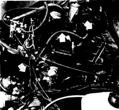
The illustration shows part of the engine of the old diesel model "Golf". Built-in special branched ventilation hose (see arrows), which prevents excess oil from entering the suction channels. At its lower end, the hose is connected to a modified flange.
Visitor comments