
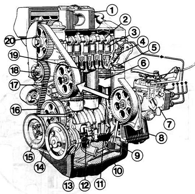
This illustration shows where the individual parts of the diesel engine are located. For clarity, the high pressure fuel pump is slightly offset in the figure. The arrow indicates where it should actually be. 1 - air filter; 2 - camshaft; 3 - cup pusher; 4 - nozzle; 5 - glow plug; 6 - piston; 7 - high pressure fuel pump; 8 - oil filter; 9 - oil pump; 10 - olive bath; 11 - connecting rod; 12 - thermostat of the cooling system; 13 - water pump; 14 - wedge-shaped belt; 15 - crankshaft V-belt pulley; 16 - intermediate shaft pulley; 17 - toothed belt; 18 - toothed belt tension roller; 19 - valve; 20 - camshaft timing belt pulley.
Engine Options
There are three models of diesel engines. While two naturally aspirated engines themselves must suck in air, the turbodiesel receives this air with the help of a turbocharger: air is forced into the cylinders by a turbine. Here are some engine data:
- 37 kW/50 HP - power developed by the suction diesel engine (1.5 l), which was installed until July 1980. Abbreviated designation SK.
- 40 kW/54 hp - suction diesel engine power (1.6 l). Its abbreviation is CR (until July 1982). Engines installed later are designated JK.
- 51 kW/70 hp - turbodiesel engine power (1.6 l) with the designation SU.
Diesel principle
As in a carburetor, in a diesel engine the pistons slide up and down in the cylinders. When the piston moves down (suction cycle) The diesel engine draws in only clean air. As the piston moves upward, the intake air is compressed. For example, in our diesel engine, the intake air is compressed to 1/23 of the volume, i.e. 23 times. Due to this huge compression, the air becomes very hot. The fact that heat is released when air is compressed can be noticed when you inflate bicycle tires. Fuel is now injected into hot air. The smallest droplets of fuel ignite on their own. Thus, a diesel does not need spark plugs to ignite the air-fuel mixture. The injection time and the amount of injected fuel is determined by the operation of the high pressure fuel pump.
As in a carbureted engine, the pressure from the combustion of the mixture moves the piston down again, with this movement work is done. The crankshaft turns, and the piston rushes up again, displacing the exhaust gases of the cylinder. The piston and cylinder are now ready to be sucked up again and repeat the work cycle.
Divided working chamber
Particles of fuel injected into the combustion chamber of a diesel engine burn at lightning speed. Therefore, there is a lot of noise during operation, the engine bearings are very heavily loaded, the engine runs hard. "Soft" combustion in a passenger car diesel engine is achieved by means of so-called divided combustion chambers.
Combustion starts in a separate swirl chamber in the cylinder head. The pressure developing in the chamber does not act on the piston immediately, but through the connecting channel. Due to this, the increase in pressure does not occur explosively, but more evenly. This achieves more "soft" and quiet diesel operation.
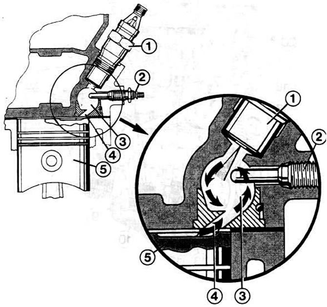
In the picture you see part of the section of the engine. From this illustration, you can understand where the swirl chamber is located in the cylinder head. On the right is an enlarged view of the area around the vortex chamber. The arrows symbolize hot air, which is squeezed out by the piston into the vortex chamber. The injected fuel, due to the rapid movement of hot air, begins to swirl and mix with air, a homogeneous fuel-air mixture is formed, which ignites well. 1 - nozzle; 2 - glow plug; 3 - vortex chamber; 4 - channel; 5 - piston.
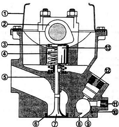
Diesel engine cylinder head section: 1 - valve cover; 2 - camshaft; 3 - setting plate for adjusting the thermal clearance of the valve; 4 - valve spring; 5 - valve guide sleeve; 6 - valve seat; 7 - valve; 8 - channel; 9 - vortex chamber insert; 10 - vortex chamber insert retainer; 11 - hole for a glow plug; 12 - hole for the nozzle; 13 - cup pusher.
Vortex chamber
Since it became possible to create a divided working chamber in a diesel engine, designers "Volkswagen" chose the principle of the vortex chamber. The drawings on pages 24 and 25 show sections of the swirl chamber. The swirl chamber located in the cylinder head is connected to the combustion chamber via the relatively wide channel already mentioned. When the piston in the compression phase rushes up, the air in the cylinder is directed into the vortex chamber. There begins the vortex movement of air. Fuel is injected through the nozzle, it mixes with air, sprays and burns. Thus, we see that combustion mainly occurs in the vortex chamber, and then continues in the combustion chamber. During operation, the chamber becomes very hot and becomes red-hot. But it is precisely this effect that is desirable, since in this way the colliding fuel particles are best atomized.
Some diesel engine manufacturers use a so-called prechamber instead of a swirl chamber, for example, in cars "Mercedes Benz". The prechamber is much more separated from the combustion chamber. Without going into details of the working process, we can note an effect similar to vortex-chamber mixing - "soft" work', low noise and vibration, especially at low speeds.
Visitor comments