



The adjustable cylinders should have the camshaft eccentrics facing up (OT). Now turn the corresponding cup tappets so that they are accessible from the right and left.
Turn the crankshaft further by 1/4 turn. The piston is then no longer at the top dead center. Therefore, the valves cannot collide with it when the cup tappet is pressed down with a key.
Place the key between both cams of the corresponding cylinder; both cup plungers are pressed down simultaneously.
Place special pliers on the cutouts of the cup pusher and lift the mounting plate.
When installed correctly, the washer is positioned in the cup tappet so that its thickness marking is at the bottom.
If the washer is inserted incorrectly, the numbers on it will no longer be visible after the engine has been running.
The thickness of the washer should be calculated (see next section).
Place the new washer into the cup plunger so that the numbers are at the bottom.
Selecting a shim
If it is necessary to change the thermal clearance, then the washer for the exhaust valve is selected in such a way that the upper tolerance value of 0.50 mm is achieved due to the high temperatures that occur. For the intake valve, we set the average tolerance value of 0.25 mm. If the clearance is too small, then a thinner adjusting washer is needed. If the clearance is too large, the washer must be thicker.
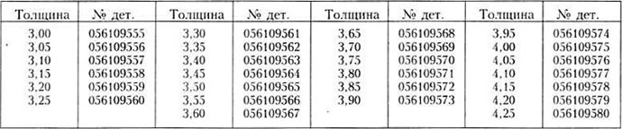
We give two examples (table 1). The following mounting plates are available (table 2).
Note: The new valve cover gasket and the cover itself must be installed very carefully, otherwise oil may leak out. Don't forget about the gasket under the valve cover locknuts!
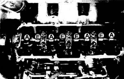
In a diesel engine, the valves are located next to each other in the cylinder head. The order of the inlet (E) and outlet (A) valves is A-E-A-E-E-A-E-A. For best heat distribution, the outlet valves are located on the outside of the engine.
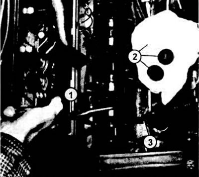
The illustration shows the adjustment of the valves of a diesel engine. The key (3) is pressed down on the cup tappets. In this way, the installation plates (2) can be replaced using special pliers (1). When the plate is mounted, its size must be indicated at the bottom
Table 1

Table 2
Visitor comments