
English Русский
Български
Беларускі
Український
Српски
Hrvatski
Română
Polski
Slovenský
Magyar
  |  Articles  |  Sitemap  |  Contacts  |    |
Car maintenance Ford Car maintenance Hyundai Car maintenance Chevrolet Car maintenance BMW Car maintenance Audi Car maintenance Opel Car maintenance AvtoVAZ
VWmanual.ru


Main   Passat   Golf   Polo   Touareg   Tiguan   Sharan   Transporter   Others  
Golf 1 (1974-1984, diesel) Golf 1 (1974-1984, petrol) Golf 2 (1984-1993, petrol) Golf 2 (1984-1993) Golf 3 (1991-1997) Golf 4 (1997-2004) Golf 5 (2003-2008)

Disassembling the instrument panel (VW Golf 1)

  • Main
  • Golf
  • Golf 1
  • Electrical equipment
  • Equipment and devices
  • Disassembling the instrument panel
            0


Contents: Removal the conductive film ↓ Dismantling the printed circuit…↓ Replacing the printed circuit board…↓ Replacing LEDs ↓ Removal instruments in the Golf…↓ Removal instruments in Golf and…↓ Removal console instruments ↓
Doing the panel yourself is possible without any problems. But when buying parts, you should take into account that there are countless options for printed circuit boards, connectors, devices, etc. If someone wants to install used parts, they should take into account: they must be from a car of the same year of manufacture.

Note: The failure of the device is often caused by the fact that the board or the track on it is damaged. Defects that arise from high temperature are very typical.

Removal the conductive film


Place the instrument panel face down.

Remove the sockets of the instrument lighting device and indicator lamps.

Unscrew the fastening screw of the voltage stabilizer. Read about installation further in this chapter.

If the board is changed, the stabilizer must be pulled out of its contacts.

Loosen the nuts (SW7 and SW5) of the threaded pins of the device.

Place the spacer rings aside and then reinstall them in the same place.

Unscrew the mounting screws of the board, paying attention to the possible insulating washer, which should be laid again in the same place.

Dismantling the printed circuit board in a Golf model produced before July 1980.


Remove the connector from the watch.

Disengage the multi-pin connector holder behind the panel. To do this, use a small screwdriver to slightly move the clamp near the holder on the narrow side.


Carefully remove the board from the plastic clips using a screwdriver.

Replacing the printed circuit board in the "Golf" model produced after August 1980 and in the "Jetta" model


Remove the plug from the board near the clock.

Unscrew the screw near the clock.

Carefully lift the board from the connections to the plate with the diodes. Do not pull the board, place a flat screwdriver under it and move it upwards.

Remove the board completely without bending it.

When installing the board, pay attention to the fact that near the clock the connecting connector lies under the contact eye. Otherwise, the board will be warped.

Replacing LEDs


In the instrument cluster of the Jetta model produced before July 1980, it is not possible to replace an individual LED.

Remove the board.

Raise the middle support.

In the middle of the plate with diodes, carefully lift the black diode holder (picture bottom left).
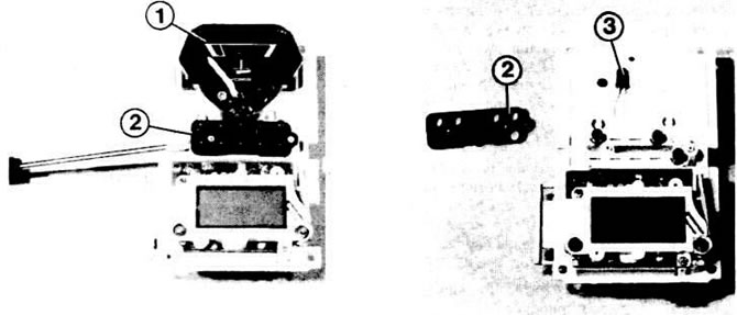
Left: Using a small screwdriver, lift up the diode holder (2). The temperature indicator (1) is…

Left: Using a small screwdriver, lift up the diode holder (2). The temperature indicator (1) is inserted

Right: The elongated LED (3) is visible.


Remove the defective diode and insert a new one.

Do not mix up the connections of the diodes: the negative terminal to the diode is slightly wider. In some versions, the mounting location is stamped on the plate with the diodes.


To replace the LED in the switch indicator, you must first remove it from the white plate with diodes.
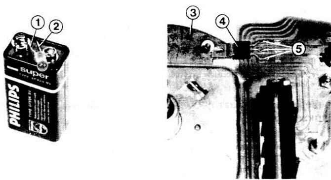
Left: Testing a LED with a 9V battery. The straight clamp (2) is connected to the positive…

Left: Testing a LED with a 9V battery. The straight clamp (2) is connected to the positive terminal; the bent clamp (1) is connected to the minus.

Right: the voltage stabilizer (4) is inserted into the board with its three contacts (5); it is mounted on the cooling plate or housing (3) of the tachometer.


Removal instruments in the Golf model produced before July 1980.


depending on the year of manufacture and equipment options, removal may vary.

Remove the incandescent lamp holders, voltage stabilizer, and board.

Loosen the 4 mounting screws in the tachometer.

Loosen the tachometer housing mounting screws; remove the fuel gauge.

Clock, fuel gauge and temperature gauge. Remove the tachometer.

Loosen both mounting screws located on the outside of the instrument panel housing (these are the screws of the white support plates). Also unscrew the screws connecting the clock and the support plates.

Remove the support plates together with the instruments inside. Be careful not to catch the hands, as they may bend.

Removal instruments in Golf and Jetta models produced after August 1980.


First of all, you need to remove the devices located in the middle.

Remove the board.

To remove the temperature gauge and switches located in the middle, you need to lift the middle support of the instruments.

Remove the complete set of devices from the support.

Remove the speedometer housing.

Disconnect the speedometer shaft mounting screws and pull it out.

If necessary, remove the fuel gauge located on the right.

Remove the watch.

To remove the fuel gauge and temperature gauge located on the right, unscrew the two frame mounting screws.

Remove the corresponding device from the support.

Removal console instruments


Remove the console (see chapter "Salon").

Remove the two knurled nuts on the back of the console.

Remove the connector; remove the instruments.

This article is available at russian, bulgarian, belarusian, ukrainian, serbian, croatian, romanian, polish, slovak, hungarian
The text has been checked: Medvedeva Elena

Share information:

Previous articles
Replacing the lamps that illuminate the devices
Removal the instrument panel
Checking control instruments and bulbs
Fuses with regular and flat plugs
Electrical Wires — General Information
Electrical engineering and electronics — general description
Next articles
Voltage stabilizer — check and replacement
Fuel level sensor — check
Coolant temperature gauge
Shift indicator
Speedometer (speed indicator)
Removal the flexible shaft of the speedometer drive


Similar articles from other manuals for VW cars:
Instrument panel Passat B3 (1988-1993)
Instrument panel Polo 3 (1995-2003)
Black and white display in the instrument cluster Touareg 1 (2002-2006)
Disassembling the engine Tiguan 1 (2007-2015)
Disassembling the cylinder head Sharan 1 (1995-2000)
Instrument visor (dashboard) on the instrument panel Transporter T4 (1990-2003)
Instrument panel — removal and installation Beetle (1960-1986)
Link to this page in different formats


Visitor comments


No comments yet


How much will 42 + 20 =


Golf 5 
  • General information
  • User manual
  • Maintenance
  • Troubleshooting
  • Power unit
  • Engine repair
  • Cooling and ventilation system
  • Fuel system
  • Ignition system
  • Transmission
  • Clutch
  • Mechanical gearbox
  • Automatic gearbox
  • Chassis
  • Brake system
  • Car suspension
  • Steering
  • Body
  • Interior (internal elements)
  • Exterior (external elements)
  • Doors and covers
  • Electrical equipment
  • Power devices
  • Washers and wipers
  • Lighting and appliances
  • Electrical circuits
Golf 4 
  • General information
  • User manual
  • Weekly checks
  • Maintenance
  • Power unit
  • Petrol engines
  • Diesel engines
  • Cooling system
  • Fuel system (petrol)
  • Control system (petrol)
  • Fuel system (diesel)
  • Exhaust system
  • Transmission
  • Clutch
  • Car gearbox
  • Drive shafts
  • Chassis
  • Car suspension
  • Steering
  • Wheels and tires
  • Brake system
  • Body
  • Exterior (external elements)
  • Interior (internal elements)
  • Ventilation and heating
  • Car doors and sunroof
  • Washers and glass cleaners
  • Electrical equipment
  • Power devices
  • Lighting and appliances
  • Electrical circuits
Golf 3 
  • Petrol engine
  • Engine repair
  • Lubrication system
  • Cooling system
  • Ignition system
  • Diesel engine
  • Engine repair
  • Diesel injection system
  • Pre-glow system
  • Transmission
  • Clutch
  • Gearbox and drive shafts
  • Chassis
  • Steering
  • Wheels and suspension
  • Brake system
  • Electrical equipment
  • Lighting and appliances
  • Electrical circuits
Golf 2 
  • General information
  • Introduction to guide
  • User manual
  • Petrol engines 1.3 l
  • Engine repair
  • Lubrication system
  • Cooling system
  • Carburetors
  • Supply system
  • Ignition system
  • Petrol engines 1.6/1.8 l
  • Engine repair
  • Supply system
  • Ignition system
  • Diesel engines
  • Engine repair
  • Lubrication system
  • Cooling system
  • Power and exhaust system
  • Transmission
  • Clutch
  • 4-speed gearbox 084
  • 5-speed gearbox 085
  • 4-speed gearbox 020/4R
  • 5-speed gearbox 020/4T
  • Automatic gearbox
  • Drive shafts
  • Chassis
  • Steering
  • Car suspension
  • Brake system
  • Body
  • Body elements
  • Doors, locks and windows
  • Electrical equipment
  • Equipment and devices
  • Power devices
Golf 2 (petrol) 
  • General information
  • Characteristics
  • Car care
  • Maintenance
  • Power unit
  • Engine repair
  • Engine 1.05/1.30
  • Engine 1.60/1.80
  • Cooling and lubrication system
  • Power and exhaust system
  • Transmission
  • Clutch
  • Car gearbox
  • Drive shafts
  • Chassis
  • Brake system
  • Steering
  • Suspension
  • Body
  • Body and equipment
  • Electrical equipment
  • Lighting and appliances
  • Electrical circuits
Golf 1 (petrol) 
  • General information
  • Characteristics
  • User manual
  • Maintenance
  • Power unit
  • Engine adjustment
  • Engine 1.1/1.3
  • Engine 1.5/1.6/1.8
  • Engine electrical equipment
  • Cooling system
  • Fuel system
  • Transmission
  • Clutch and manual gearbox
  • Automatic gearbox
  • Chassis
  • Steering
  • Front suspension
  • Rear suspension
  • Brake system
  • Electrical equipment
  • Lighting and appliances
  • Electrical circuits
  • Body
  • Body and equipment
  • Optional equipment
Golf 1 (diesel) 
  • General information
  • Specifications
  • Maintenance
  • Power unit
  • Engine repair
  • Exhaust and turbocharger
  • Cooling system
  • Fuel system
  • Fuel injection system
  • Transmission
  • Clutch and drive shafts
  • Car gearbox
  • Chassis
  • Suspension and wheels
  • Steering
  • Brake system
  • Wheels and tires
  • Body
  • Heating and ventilation
  • Exterior (external elements)
  • Interior (internal elements)
  • Doors and windows
  • Electrical equipment
  • Equipment and devices
  • Lighting system
  • Power devices
  • Electrical circuits
VWmanual.ru © 2016-2026 | Mobile version | News and articles | Sitemap: EN BG BY UA RS HR RO PL SK HU | Write message | Site search
Passat B2 • Passat B3 • Passat B4 • Passat B5 • Passat B6 • Golf 1, diesel • Golf 1, petrol • Golf 2, petrol • Golf 2 • Golf 3 • Golf 4 • Golf 5 • Polo 3 • Polo 4 • Touareg 1 • Tiguan 1 • Sharan 1 • Transporter T3 • Transporter T4 • LT 28 • LT 2D • Beetle • Caddy 3 •
Our website uses cookies to ensure functionality and convenience.