
Remove dashboard.
Turn the bulb holder 1/4 turn and remove (see fig. left).
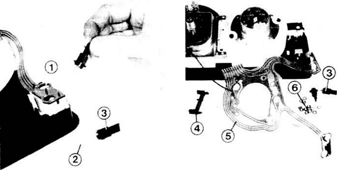
Left: for lighting fixtures in the housing (1) placed lamp (2) with glass base and socket (3). Right: conductive track (5) with fixing clip (4), as well as nuts and o-rings (6).
Replacing control bulbs
Models "Golf" releases before July 1980 have conventional light bulbs with a glass base. In the model "Jetta", released before July 1980, a conventional lamp is used to control the high beam. Replacement is carried out in the same way as indicated earlier. The new instrument cluster uses a glass-base bulb as the brake light indicator. Replacement is carried out as previously indicated.
In the new instrument panel, LEDs are installed as control lights, see section "Semiconductors", chapter "electrical and Electronics". To protect against too high voltages, each LED is connected to its own resistance. The battery monitor LED also has an additional 150 ohm resistance to pre-excite the alternator, see chapter "Generator", chapter "Battery monitor". To dismantle the LEDs of the combined instrument, it is necessary to disassemble it.
Coolant temperature gauge with red or yellow flashing lights in the model "Golf" production from August 1979 to July 1980 also has such LEDs. To replace the LEDs, it is enough to remove the instrument panel.
Brake system warning light: remove the instrument panel bezel.
Squeeze together the fixing clips of the lamp housing; remove the frame from the frame.
Take out the defective light bulb (1.2W) with a glass base and replace it with a new one.
In the latest models, the lamps are soldered to the body; In this case, you need to buy a new housing with a lamp.
Temperature control lamps: remove the instrument panel.
Take out the lamp sockets.
Remove the printed circuit board at the back, near the lamp housing.
Remove the defective LED from its contact tabs. Insert the new LED again in the same position.
The positive leads of the LEDs are marked. Red LED: additional short pin right at the stand Yellow LED: The connection at the stand is narrower than near the negative terminal.
Near the printed circuit board is the negative contact of the LEDs: right under the holes for the lamp holders.
Visitor comments