
English Русский
Български
Беларускі
Український
Српски
Hrvatski
Română
Polski
Slovenský
Magyar
  |  Articles  |  Sitemap  |  Contacts  |    |
Car maintenance Ford Car maintenance Hyundai Car maintenance Chevrolet Car maintenance BMW Car maintenance Audi Car maintenance Opel Car maintenance AvtoVAZ
VWmanual.ru


Main   Passat   Golf   Polo   Touareg   Tiguan   Sharan   Transporter   Others  
Golf 1 (1974-1984, diesel) Golf 1 (1974-1984, petrol) Golf 2 (1984-1993, petrol) Golf 2 (1984-1993) Golf 3 (1991-1997) Golf 4 (1997-2004) Golf 5 (2003-2008)

Master brake cylinder (VW Golf 1)

  • Main
  • Golf
  • Golf 1
  • Chassis
  • Brake system
  • Master brake cylinder
            0


Contents: Replacing the Master Cylinder -…↓ Replacing the Master Cylinder -…↓ Replacing seals ↓

Replacing the Master Cylinder - Models with Brake Servo


1. Before removing the master cylinder, remove the brake fluid from the reservoir by sucking it out with a siphon or by opening the bleeder nipples on the brake calipers and pressing the brake pedal several times. After removing the fluid, tighten the bleeder nipples.

2. Disconnect the wire connectors from the brake light switches on the master cylinder.

3. Disconnect the brake pipes from the master cylinder body. Mark the position of the pipes with tags to ensure their correct installation later. Plug the outlet ports of the brake cylinder and the ends of the pipes to prevent fluid loss and dirt ingress.

4. Remove the two nuts (13mm) and washers securing the master cylinder to the servo booster, then remove the master cylinder by sliding it forward.

5. Remove the cap from the reservoir and pour out the remaining brake fluid.

6. Install the master cylinder in the reverse order. Install a new sealing ring under the master cylinder.

7. After installing the cylinder, fill the reservoir with new brake fluid and bleed the brake system as described earlier.

Replacing the Master Cylinder - Models Without Brake Booster


The master brake cylinder is mounted directly on the rear bulkhead of the engine compartment, opposite the brake pedal.

Replacing the cylinder is done in the same way as on models with servo assistance. After unscrewing the nuts, slide the cylinder forward to remove it from the pedal pusher.


When installing the cylinder, make sure that the pedal pusher enters through the boot hole into the recess of the primary piston of the master cylinder.

If necessary, adjust the pushrod length so that the brake pedal free play is 3 mm.

Replacing seals


The master cylinders on models with and without servo amplifiers differ only in the design of the pushrod (drawing O:22).
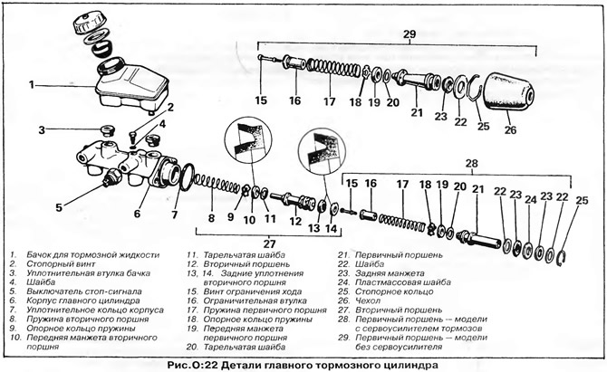
The master cylinders on models with and without servo amplifiers differ only in the design of the…


The master cylinder can be one of the following types: "ATE" (Teves), "FAG" (Schafer) or "Bendix" (Bendix). When purchasing a repair kit, you need to know the type of master cylinder.

1. Carefully pry the brake fluid reservoir off the top of the master cylinder. Remove the rubber seals from the cylinder inlet ports.

2. Unscrew the brake light switches from the cylinder body.

3. Remove the locking screw at the top of the cylinder body - the screw is located between the inlet holes.

4. Remove the retaining ring from the rod side of the cylinder, then remove the pistons.

5. Unscrew the stroke limiting screw from the end of the primary piston and remove the limiting sleeve, spring and other parts. Remove the seals from both pistons.


6. Clean the master cylinder and pistons with methylated spirits or clean brake fluid. Do not use mineral-based fluids such as gasoline or kerosene. Dry the parts with a lint-free cloth or blow them with compressed air.

7. If the pistons and cylinder are in good condition, assemble the master cylinder as follows:

8. Lubricate the pistons, piston seals and cylinder with clean brake fluid.

9. Install new seals on the secondary (front) piston. Install the disc washer on the conical end of the piston, then the front seal with the flat surface against the piston shoulder (drawing O:22). Install the two secondary piston rear seals into the grooves on the rear end of the piston with the flat sides facing each other. It is advisable to use a mounting sleeve to install the seals (drawing O:21), and if it is not there, be very careful not to damage the seals on the sharp edges of the piston grooves.
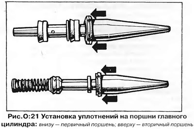
9. Install new seals on the secondary (front) piston. Install the disc washer on the conical end of…


10. Install the support ring and conical spring onto the rear end of the secondary piston (not to be confused with primary piston coil spring).

11. Install new seals on the primary (rear) piston. Install the front seal with the washer on the short lip on the front side of the piston with the flat surface facing the piston (drawing O:22). On non-powered models, install the single rear seal into the groove on the rear end of the piston with the flat surface facing back. On powered models, install the two rear seals with washers onto the long extension on the rear end of the piston with the flat surfaces facing away from the piston. The installation sequence should be: flat washer, seal, plastic washer, seal, and flat washer.

12. Assemble the support ring, coil spring and limit sleeve at the front end of the primary piston, and secure the parts with the stroke limit screw.

13. Insert the secondary and then the primary piston assemblies into the master cylinder body, guiding the sealing edges of the cuffs with a screwdriver.

14. Press the pistons into the cylinder and install the retaining ring into the groove at the end of the cylinder.

15. Screw the lock screw into the cylinder body from the top while holding the pistons in a depressed state, then release the pistons.

16. On models without power steering, install the rubber boot on the master cylinder.

17. Wet the two rubber seals of the reservoir with brake fluid and press them into the inlet holes of the cylinder. Press the brake fluid reservoir into the seals.


18. Screw the brake light switches into the cylinder body.

NOTE: The brake light switch, which screws into the side of the master cylinder, usually has two terminals for wiring, but vehicles with dual hydraulic warning lights have a three-terminal switch.


19. Install the master cylinder to the vehicle as described above and bleed the brake system. Press the brake pedal and hold it for approximately ten seconds. Inspect the master cylinder for fluid leaks.

This article is available at russian, bulgarian, belarusian, ukrainian, serbian, croatian, romanian, polish, slovak, hungarian
The text has been checked: Tarasov Ivan

Share information:

Previous articles
Rear brake cylinders
Replacing rear drum brake pads
Front Brake Calipers (VW Mk II)
Front brake calipers (Girling)
Front brake calipers (Teves)
Bleeding the brake system (removing air)
Next articles
Brake servo booster
Brake pressure regulator
Handbrake
Possible malfunctions of the brake system


Similar articles from other manuals for VW cars:
Removal and installation the brake master cylinder Passat B2 (1981-1988)
Brake master cylinder and brake booster Polo 3 (1995-2003)
Removal and installation the master brake cylinder Touareg 1 (2002-2006)
Connecting brake pipes from the master cylinder to the hydraulic… Tiguan 1 (2007-2015)
Master Brake Cylinder — General Information Sharan 1 (1995-2000)
Wheel brake cylinder — removal and installation Transporter T4 (1990-2003)
Vacuum booster and brake master cylinder LT 2D (1996-2003)
Link to this page in different formats


Visitor comments


No comments yet


How much will 31 + 23 =


Golf 5 
  • General information
  • User manual
  • Maintenance
  • Troubleshooting
  • Power unit
  • Engine repair
  • Cooling and ventilation system
  • Fuel system
  • Ignition system
  • Transmission
  • Clutch
  • Mechanical gearbox
  • Automatic gearbox
  • Chassis
  • Brake system
  • Car suspension
  • Steering
  • Body
  • Interior (internal elements)
  • Exterior (external elements)
  • Doors and covers
  • Electrical equipment
  • Power devices
  • Washers and wipers
  • Lighting and appliances
  • Electrical circuits
Golf 4 
  • General information
  • User manual
  • Weekly checks
  • Maintenance
  • Power unit
  • Petrol engines
  • Diesel engines
  • Cooling system
  • Fuel system (petrol)
  • Control system (petrol)
  • Fuel system (diesel)
  • Exhaust system
  • Transmission
  • Clutch
  • Car gearbox
  • Drive shafts
  • Chassis
  • Car suspension
  • Steering
  • Wheels and tires
  • Brake system
  • Body
  • Exterior (external elements)
  • Interior (internal elements)
  • Ventilation and heating
  • Car doors and sunroof
  • Washers and glass cleaners
  • Electrical equipment
  • Power devices
  • Lighting and appliances
  • Electrical circuits
Golf 3 
  • Petrol engine
  • Engine repair
  • Lubrication system
  • Cooling system
  • Ignition system
  • Diesel engine
  • Engine repair
  • Diesel injection system
  • Pre-glow system
  • Transmission
  • Clutch
  • Gearbox and drive shafts
  • Chassis
  • Steering
  • Wheels and suspension
  • Brake system
  • Electrical equipment
  • Lighting and appliances
  • Electrical circuits
Golf 2 
  • General information
  • Introduction to guide
  • User manual
  • Petrol engines 1.3 l
  • Engine repair
  • Lubrication system
  • Cooling system
  • Carburetors
  • Supply system
  • Ignition system
  • Petrol engines 1.6/1.8 l
  • Engine repair
  • Supply system
  • Ignition system
  • Diesel engines
  • Engine repair
  • Lubrication system
  • Cooling system
  • Power and exhaust system
  • Transmission
  • Clutch
  • 4-speed gearbox 084
  • 5-speed gearbox 085
  • 4-speed gearbox 020/4R
  • 5-speed gearbox 020/4T
  • Automatic gearbox
  • Drive shafts
  • Chassis
  • Steering
  • Car suspension
  • Brake system
  • Body
  • Body elements
  • Doors, locks and windows
  • Electrical equipment
  • Equipment and devices
  • Power devices
Golf 2 (petrol) 
  • General information
  • Characteristics
  • Car care
  • Maintenance
  • Power unit
  • Engine repair
  • Engine 1.05/1.30
  • Engine 1.60/1.80
  • Cooling and lubrication system
  • Power and exhaust system
  • Transmission
  • Clutch
  • Car gearbox
  • Drive shafts
  • Chassis
  • Brake system
  • Steering
  • Suspension
  • Body
  • Body and equipment
  • Electrical equipment
  • Lighting and appliances
  • Electrical circuits
Golf 1 (petrol) 
  • General information
  • Characteristics
  • User manual
  • Maintenance
  • Power unit
  • Engine adjustment
  • Engine 1.1/1.3
  • Engine 1.5/1.6/1.8
  • Engine electrical equipment
  • Cooling system
  • Fuel system
  • Transmission
  • Clutch and manual gearbox
  • Automatic gearbox
  • Chassis
  • Steering
  • Front suspension
  • Rear suspension
  • Brake system
  • Electrical equipment
  • Lighting and appliances
  • Electrical circuits
  • Body
  • Body and equipment
  • Optional equipment
Golf 1 (diesel) 
  • General information
  • Specifications
  • Maintenance
  • Power unit
  • Engine repair
  • Exhaust and turbocharger
  • Cooling system
  • Fuel system
  • Fuel injection system
  • Transmission
  • Clutch and drive shafts
  • Car gearbox
  • Chassis
  • Suspension and wheels
  • Steering
  • Brake system
  • Wheels and tires
  • Body
  • Heating and ventilation
  • Exterior (external elements)
  • Interior (internal elements)
  • Doors and windows
  • Electrical equipment
  • Equipment and devices
  • Lighting system
  • Power devices
  • Electrical circuits
VWmanual.ru © 2016-2026 | Mobile version | News and articles | Sitemap: EN BG BY UA RS HR RO PL SK HU | Write message | Site search
Passat B2 • Passat B3 • Passat B4 • Passat B5 • Passat B6 • Golf 1, diesel • Golf 1, petrol • Golf 2, petrol • Golf 2 • Golf 3 • Golf 4 • Golf 5 • Polo 3 • Polo 4 • Touareg 1 • Tiguan 1 • Sharan 1 • Transporter T3 • Transporter T4 • LT 28 • LT 2D • Beetle • Caddy 3 •
Our website uses cookies to ensure functionality and convenience.