
Instructions: Use only new brake fluid. Pay attention to hydrostatic pressure in the brake fluid reservoir!
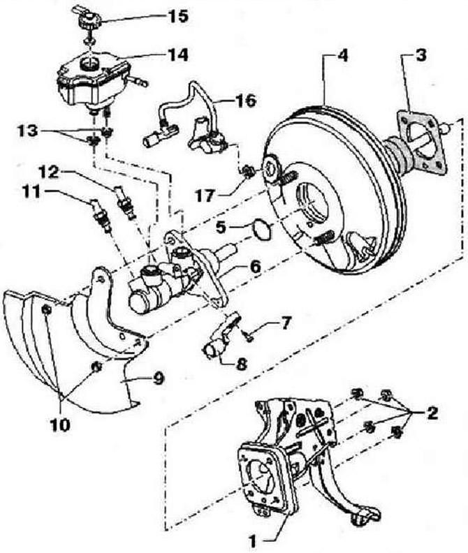
- 1 - Pedal assembly
- 2 - Hexagonal self-locking nut,
- 25 Nm, replace after each removal, first tighten from bottom left and top right
- 3 - Brake booster seal
- 4 - Brake booster, on gasoline engines the required vacuum is supplied from the intake manifold, vehicles with a 2.0 l gasoline engine are additionally equipped with a vacuum pump, vehicles for North America with a hydraulic brake booster are equipped with a vacuum sensor, in vehicles with diesel engines to create a vacuum installed a vacuum pump. Function test: with the engine off, firmly press the brake pedal several times (this will reset the residual vacuum in the amplifier), depress the brake pedal with medium force and hold it. Start the engine. When the brake booster is working properly, the brake pedal will begin to sink noticeably easier when pressed (the effect of the amplifier becomes well felt), in the event of a malfunction, it is replaced entirely (pre-check all vacuum lines)
- 5 - O-ring
- 6 - The main brake cylinder, not subject to repair, if a malfunction occurs, it is replaced entirely
- 7 - Screw Togh, 8 Nm
- 8 - Stop light switch -F-
- 9 - Heat shield
- 10 - Hexagon self-locking nut, 25 Nm, replace after each removal
- 11 - Brake pipe fitting, 14 Nm, brake master cylinder/floating cylinder circuit to hydraulic unit
- 12 - Brake pipe fitting, 14 Nm, brake master cylinder / pusher cylinder circuit to hydraulic unit
- 13 - Sealing sleeves, lubricate with brake fluid and install the brake fluid reservoir
- 14 - Compensation tank for brake fluid
- 15 - Lid
- 16 - Vacuum hose with non-return valve and additionally on vehicles with hydraulic brake booster with vacuum sensor -G608-, insert into brake booster
- 17 - Sealing sleeve, vacuum hose fitting sockets
Visitor comments