
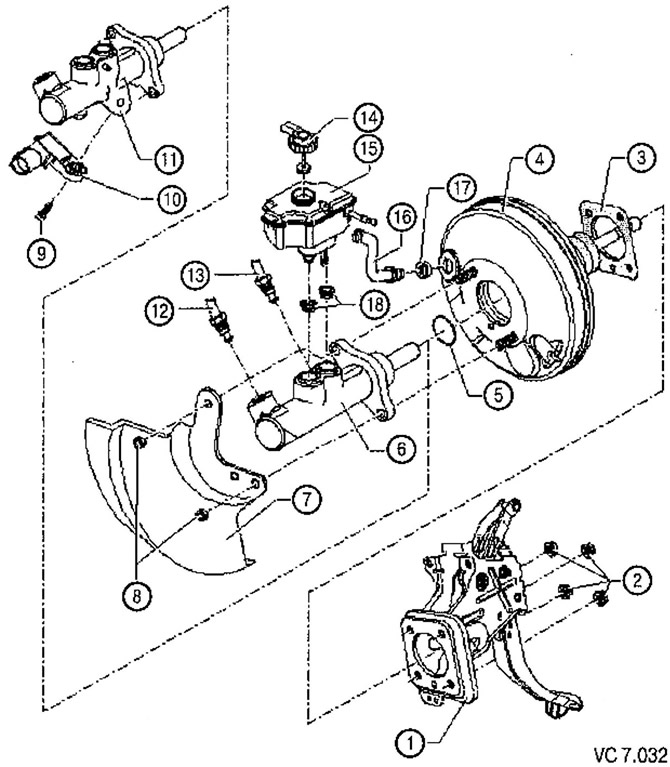
List of parts and assemblies of the main brake cylinder and brake booster with technological notes on repair to drawing VC7.032:
1. Pedal assembly.
2. Hex self-locking nut: 25 Nm:
- Replace after each removal.
3. Laying of the amplifier of brakes.
4. Brake booster:
- on gasoline engines, the required vacuum is supplied from the intake manifold;
- in diesel engines, a vacuum pump is installed to create a vacuum;
- to check with the engine off, firmly press the brake pedal several times (this will reset the residual vacuum in the amplifier), then depress the brake pedal with medium force and hold it. Start the engine. When the brake booster is working properly, the brake pedal will begin to sink noticeably easier when pressed (the effect of the amplifier becomes well felt);
- in the event of a malfunction, it is replaced entirely.
5. O-ring.
6. Dual chamber brake master cylinder without brake light switch:
- not repairable. If any malfunction occurs, it is completely replaced.
7. Heat shield.
8. Hex self-locking nut: 25 Nm:
- Replace after each removal.
9. Inner screw type Tox, tightening torque: 5 Nm.
10. Stoplight switch (F) with brake pedal sensor (F47):
- for vehicles up to model year 2007 brake light switch (F) located on the brake pedal.
11. Dual chamber brake master cylinder with brake light switch:
- not repairable. In the event of a malfunction, it is completely replaced.
12. Brake line: 14 Nm:
- from the main brake cylinder with a floating piston to the hydraulic unit.
13. Brake line: 14 Nm.
14. Lid.
15. Brake fluid reservoir.
16. Vacuum hose.
17. Seal.
18. Seals:
- Lubricate with brake fluid and install the brake fluid reservoir.
Visitor comments