
English Русский
Български
Беларускі
Український
Српски
Hrvatski
Română
Polski
Slovenský
Magyar
  |  Articles  |  Sitemap  |  Contacts  |    |
Car maintenance Ford Car maintenance Hyundai Car maintenance Chevrolet Car maintenance BMW Car maintenance Audi Car maintenance Opel Car maintenance AvtoVAZ
VWmanual.ru


Main   Passat   Golf   Polo   Touareg   Tiguan   Sharan   Transporter   Others  
LT 28 (1975-1991) LT 2D (1996-2003) Beetle (1960-1986) Caddy 3 (2003-2010)

List of parts and components of the master brake cylinder (VW Caddy 3)

  • Main
  • Volkswagen
  • Caddy 3
  • Chassis
  • Brake system
  • List of parts and components of the master brake cylinder
            0


Contents: On a dual master cylinder ↓ On the hydraulic block ↓ On a dual master cylinder ↓ On the hydraulic block ↓
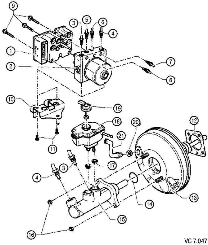
List of parts and assemblies with notes on installation work for Figure VC7.047:

List of parts and assemblies with notes on installation work for Figure VC7.047:
1. ABS control unit.
2. ABS hydraulic unit.
3. Brake line from
master brake cylinder to hydraulic unit: M10x1.
4. Brake line from the master cylinder to the hydraulic unit M12x1.
5. Brake line to the front left brake caliper M12x1.
6. Brake line to the front right brake caliper M10x1.
7. Brake line to the rear left brake caliper M12x1.
8. Brake line to the rear right brake caliper M10x1.
9. Torx screw: 5.5 Nm.
10. Bracket.
11. Hexagon head bolt: 8 Nm.
12. Brake booster gasket.
13. Brake booster:
- performance check;
- with the engine not running, press the brake pedal firmly several times (this will relieve the residual vacuum in the amplifier), then press the brake pedal with medium force and hold it; start the engine. If the brake booster is working properly, the brake pedal will become noticeably easier to press when pressed (the amplifier's effect becomes clearly noticeable);
- if a malfunction occurs, it is replaced entirely.
14. Sealing ring.
15. Dual master cylinder:
- cannot be repaired. If any malfunction occurs, it is replaced entirely.
16. Hexagon nut: 25 Nm:
- replace after each removal.
17. Seals:
- lubricate with brake fluid and install the brake fluid reservoir.
18. Brake fluid reservoir.
19. Lid.
20. Compaction.
21. Brake booster.


On a dual master cylinder
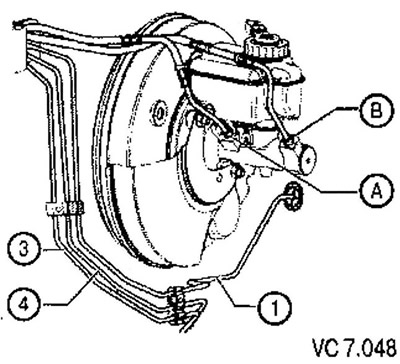


A. Connects the master cylinder pusher circuit and the M10x1 hydraulic block

A. Connects the master cylinder pusher circuit and the M10x1 hydraulic block
B. Connects the cylinder circuit and the hydraulic block M12x1
1. Connects the hydraulic unit to the front left brake caliper
2. Connects the hydraulic unit to the rear right brake caliper
3. Connects the hydraulic unit to the rear left brake caliper


The original can be viewed on the portal: www.VWmanual.ru

On the hydraulic block
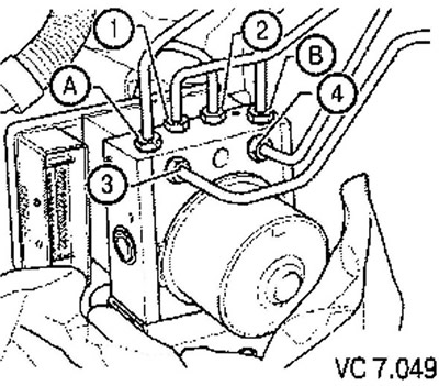


A. Connects the hydraulic unit to the master cylinder pusher circuit M10x1

A. Connects the hydraulic unit to the master cylinder pusher circuit M10x1
B. Connects the hydraulic unit to the floating cylinder circuit of the M12x1 brake master cylinder
1. From the hydraulic unit to the front left brake caliper M10x1
2. From the hydraulic unit to the front right brake caliper M10x1
3. From the hydraulic unit to the rear right brake caliper M10x1
4. From the hydraulic unit to the rear left brake caliper M10x1
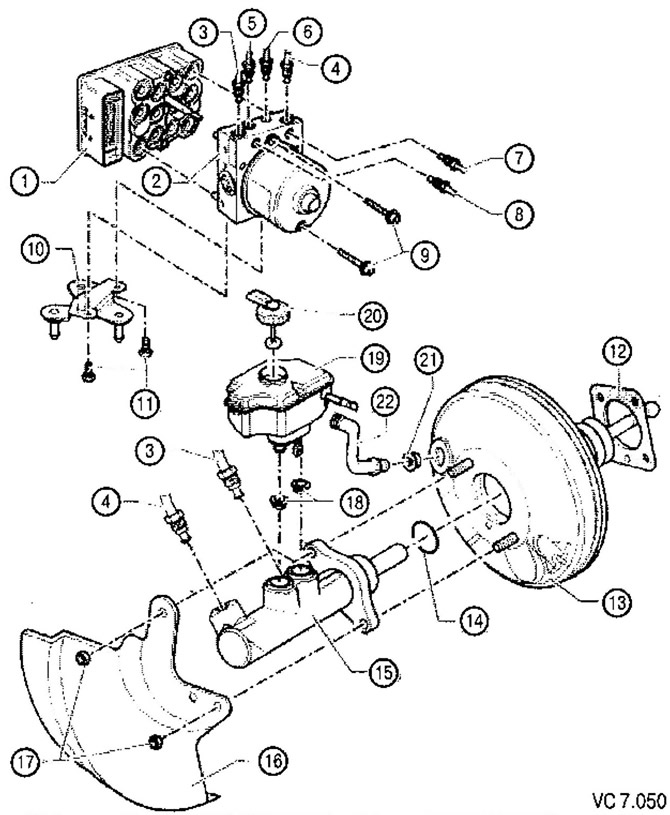


List of parts and assemblies with notes on installation work for Figure VC7.050:

List of parts and assemblies with notes on installation work for Figure VC7.050:
1. ABS control unit.
2. ABS hydraulic unit.
3. Brake line from the master cylinder to the hydraulic unit:
- features: ∅ 6.5 mm, nipple with long thread M12x1.
4. Brake line of the master cylinder to the hydraulic unit:
- features: ∅ 6.5 mm, nipple with long thread M10x1.
5. Brake line to front left brake caliper:
- features: ∅ 5.25 mm, short threaded nipple M12x1.
6. Brake line to front right brake caliper:
- features: ∅ 5.25 mm, threaded nipple M10x1.
7. Brake line to rear left brake caliper:
- features: ∅ 5.25 mm, fitting with short thread M10x1.
8. Brake line to rear right brake caliper:
- features: ∅ 3.25 mm, threaded nipple M10x1.
9. Torx screw: 5.5 Nm.
10. Bracket.
11. Hexagon head bolt: 8 Nm.
12. Brake booster gasket.
13. Brake booster.
14. Sealing ring.
15. Dual master cylinder.
18. Heat shield.
17. Hexagon nut: 25 Nm:
- replace after each removal.
18. Seals:
- lubricate with brake fluid and install the brake fluid reservoir.
19. Brake fluid reservoir.
20. Lid.
21. Compaction.
22. Vacuum hose.


On a dual master cylinder
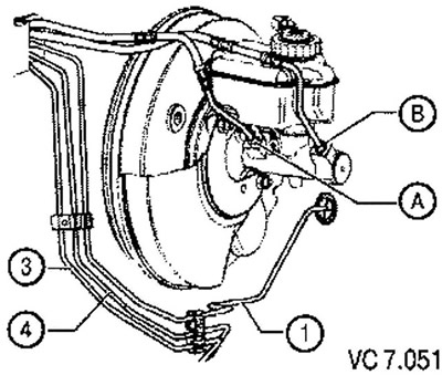


A. Connects the master cylinder pushrod circuit and the hydraulic unit: ∅ 6.5 mm, M12x1 thread

A. Connects the master cylinder pushrod circuit and the hydraulic unit: ∅ 6.5 mm, M12x1 thread
B. Connects the cylinder circuit and the hydraulic block: ∅ 6.5 mm, thread M12x1
1. Connects the hydraulic unit to the front left brake caliper
3. Connects the hydraulic unit to the rear right brake caliper
4. Connects the hydraulic unit to the rear left brake caliper


On the hydraulic block
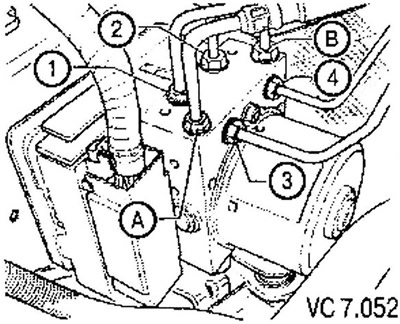


A. Connects the hydraulic unit to the master cylinder pusher circuit: ∅ 6.5 mm, long threaded…

A. Connects the hydraulic unit to the master cylinder pusher circuit: ∅ 6.5 mm, long threaded nipple M12x1
B. Connects the hydraulic unit to the floating cylinder circuit of the master brake cylinder: ∅ 6.5 mm, nipple with long thread M12x1
1. From the hydraulic unit to the front left brake caliper ∅ 5.25 mm, fitting with short thread M12x1
2. From the hydraulic unit to the front right brake caliper ∅ 5.25 mm, nipple with M10x1 thread
3. From the hydraulic unit to the rear right brake caliper: ∅ 5.25 mm, nipple with M10x1 thread
4. From the hydraulic unit to the rear left brake caliper: ∅ 5.25 mm, fitting with short thread M12x1

This article is available at russian, bulgarian, belarusian, ukrainian, serbian, croatian, romanian, polish, slovak, hungarian
The text has been checked: Kolesnikov Artem

Share information:

Previous articles
Indication of faults using indicator lamps
List of ABS Mark 60 (ABS/EDS/ASR/ESP) system components
List of components of the ABS Mark 70 (ABS/ASR) system
Exchange Rate Stability System ESP
Removal and installation the brake booster
Removal and installation the brake master cylinder
Next articles
Installation of ABS system components


Similar articles from other manuals for VW cars:
Removal and installation the brake master cylinder Passat B2 (1981-1988)
Master brake cylinder Golf 1 (1974-1984, petrol)
Brake master cylinder and brake booster Polo 3 (1995-2003)
Removal and installation the master brake cylinder Touareg 1 (2002-2006)
Brake booster/master cylinder parts and assemblies Tiguan 1 (2007-2015)
Master Brake Cylinder — General Information Sharan 1 (1995-2000)
Wheel brake cylinder — removal and installation Transporter T4 (1990-2003)
Link to this page in different formats


Visitor comments


No comments yet


How much will 19 + 46 =


Caddy 3 
  • General information
  • User manual
  • Daily care
  • Maintenance
  • Petrol engines 1.4 l
  • Engine repair
  • Cooling and lubrication system
  • Power and exhaust system
  • Petrol engines 1.6 l
  • Engine repair
  • Cooling and lubrication system
  • Power and exhaust system
  • Diesel engines
  • Engine repair
  • Cooling and lubrication system
  • Power and exhaust system
  • Transmission
  • Mechanical gearbox 0AH
  • Mechanical gearbox 0A4
  • Drive shafts
  • Chassis
  • Car suspension
  • Steering
  • Brake system
  • Body and wiring diagrams
  • Interior and exterior
  • Electrical circuits
Beetle 
  • General information
  • Maintenance
  • Power unit
  • Engine repair
  • Cooling and lubrication system
  • Supply system
  • Exhaust system
  • Transmission
  • Clutch
  • Car gearbox
  • Chassis
  • Front suspension
  • Rear suspension
  • Steering
  • Brake system
  • Wheels and tires
  • Body
  • Exterior
  • Electrical equipment
  • Equipment and devices
  • Power devices
  • Electrical circuits
LT 2D 
  • General information
  • User manual
  • Maintenance
  • Power unit
  • Petrol engines 2.3 l
  • Diesel engines 2.5 l
  • Diesel engines 2.8 l
  • Injection system (diesel 2.8 l)
  • Transmission
  • Clutch
  • Manual gearbox
  • Differential
  • Chassis
  • Car suspension
  • Steering system
  • Brake system
  • Body
  • Body elements
  • Heating system
  • Electrical equipment
  • Equipment and devices
  • Electrical circuits
LT 28 
  • General information
  • Maintenance
  • Power unit
  • Petrol engines 2.0L
  • Petrol engines 2.4L
  • Diesel engines
  • Cooling and heating
  • Fuel and exhaust system
  • Ignition system
  • Transmission
  • Clutch
  • Car gearbox
  • Cardan shaft
  • Rear axle
  • Chassis
  • Brake system
  • Car suspension
  • Steering system
  • Body
  • Body elements
  • Doors, locks and windows
  • Electrical equipment
  • Power devices
  • Equipment and devices
  • Electrical circuits
VWmanual.ru © 2016-2026 | Mobile version | News and articles | Sitemap: EN BG BY UA RS HR RO PL SK HU | Write message | Site search
Passat B2 • Passat B3 • Passat B4 • Passat B5 • Passat B6 • Golf 1, diesel • Golf 1, petrol • Golf 2, petrol • Golf 2 • Golf 3 • Golf 4 • Golf 5 • Polo 3 • Polo 4 • Touareg 1 • Tiguan 1 • Sharan 1 • Transporter T3 • Transporter T4 • LT 28 • LT 2D • Beetle • Caddy 3 •
Our website uses cookies to ensure functionality and convenience.