



118. If there are cracks between the valve seats or the valve seats and spark plug holes, you should consult a specialist regarding the further possibility of using the head.
119. Below is the procedure for removing the head from an engine removed from a car.
120. Remove the timing belt.
121. Remove the camshaft sprocket.
122. Remove the rear timing belt shield.
133. Remove the valve cover.
124. Remove the intake and exhaust manifolds (the carburetor can be left on the intake manifold).
125. Note: Before removing the cylinder head bolts, make sure the head is cold to reduce the risk of deformation. Gradually, in the reverse order of tightening, loosen the cylinder head bolts (this is necessary to further reduce the risk of head deformation) (see Figure 13.8).
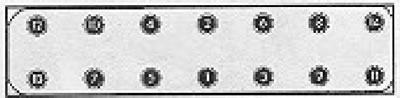
Figure 13.8. Cylinder head bolt tightening sequence (Section 4B).
126. When installing the cylinder head, always replace the gasket and head bolts with new ones.
127. Clean the contact surfaces of the cylinder head and block, removing all traces of the old gasket. Check that both surfaces are dry.
128. Special guide pins are available for sale to help align the cylinder head correctly during installation.
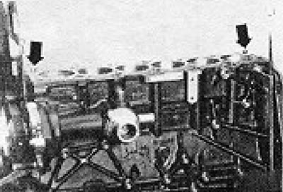
Figure 13.9. Cylinder head guide pins (shown by arrows) (section 4B).
129. In principle, similar pins can be made independently by cutting off the heads of two old cylinder head bolts and making a cut in the open ends of the resulting pins so that they can be removed later.
130. Insert guide pins into holes for bolts No. 12 and 14 (see Figure 13.8) on the cylinder block.
131. Check that the rubber insert is inserted into the new cylinder head gasket (see photo) and then install the gasket (dry) on the guide pins on the cylinder block.
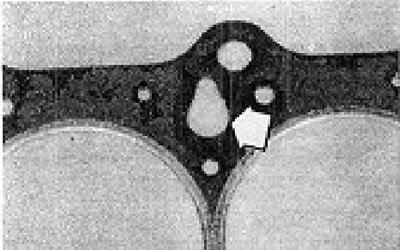
Photos 4B.131. Check that the rubber insert (shown by the arrow) was installed in the cylinder head gasket.
132. The OBEN inscription on the gasket or its number must face upwards.
133. Check that the TDC mark on the flywheel is aligned with the mark on the clutch housing.
134. Turn the camshaft so that the marks on the rear surface of the camshaft sprocket and the cylinder head are aligned.
135. Carefully lower the head onto the cylinder block (on the guide pins) (see photo).
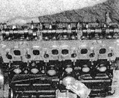
Photo 4B.135. Carefully lower the cylinder head onto the block.
136. After each removal of the head, its bolts should be replaced with new ones.
137. Install new bolts into all free holes and tighten them lightly. Remove the guide pins and replace them with bolts.
138. Tighten the cylinder head bolts in the sequence shown in Figure 13.8, following the steps specified in the Specifications. Additional tightening of the bolts by 180° should be done in one go, although in principle it is possible to tighten the bolts 2 times by 90° (see photo).
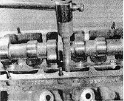
Photo 4B.138. Tightening the cylinder head bolts.
139. Connect all disconnected parts.
140. After completing the overhaul, start the engine, bring it to normal operating temperature, then turn it off and tighten all the bolts another 90° (1/4 turn) in the same sequence.
141. After the first 1000 km of mileage, the bolts should be tightened by another 90° (1/4 turn) in the same sequence.
142. The above operation can be performed on both a cold and a warm engine.
Visitor comments