



12. The engine widely uses bolts with a hole in the head for hexagonal socket heads, so before starting work you should stock up on a set of appropriate keys.
13. When removing engine attachments, see. the relevant sections of the main text and the Appendix.
14. Remove the driver and passenger seats.
15. Disconnect the negative and positive wires from the battery. For greater reliability, remove the battery.
16. Open the engine cover (see photos), disconnect the ground wire from the valve cover (see photo) and remove the lid.
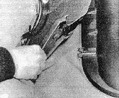
Photo 4B.16A. Lift the rubber mat.
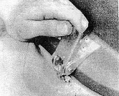
Photo 4B.16B. Loosen the clamps.
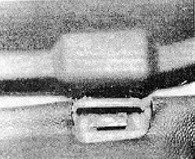
Photo 4B.16C. Lift the cover off the hinge blocks.
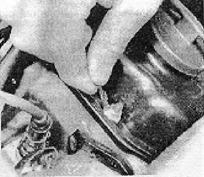
Photo 4B.16D. Disconnecting the engine cover ground wire.
17. Working under the vehicle, remove the engine mudguards.
18. Drain the fluid from the cooling system.
19. Drain the oil from the engine and gearbox.
20. Remove the upper and lower air deflector plates, the fan and its casing (see section 5).
21. Disconnect the wiring and remove the starter (see photos).
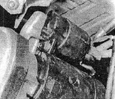
Photo 4B.21A. Starter with wires connected to it.
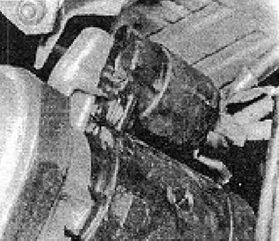
Photo 4B.21B. Starter mounting bolts.
22. Mark the position of the propeller shaft relative to the rear axle flanges.
23. Loosen the bolts securing the propeller shaft to the rear axle and pull the shaft back to remove it from the gearbox.
24. Cover the hole for the cardan shaft in the gearbox to prevent dirt from getting into the gearbox.
25. Disconnect the exhaust pipes from the exhaust manifold.
26. Disconnect the exhaust system support bracket on the gearbox (see photo).
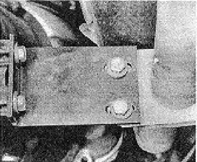
Photo 4B.26. Support bracket for fastening the exhaust pipe to the gearbox.
27. Disconnect the clutch cable from the clutch release lever. The cap and return spring have been removed (see photos).
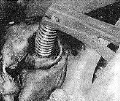
Photo 4B.27. The location where the clutch cable is attached to the clutch release lever.
28. Remove the clutch cable adjusting nut and disconnect the cable from the gearbox (see photo).
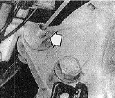
Photo 4B.28. Clutch cable adjusting nut (shown by the arrow).
29. Disconnect the gearbox ground wire.
30. Disconnect the gear shift lever bracket from the gearbox. Disconnect the gear shift rod.
31. Disconnect the speedometer cable from the gearbox and plug the resulting hole (see photos).
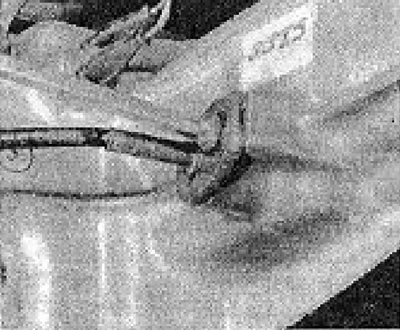
Photo 48.31A. Remove the screw...
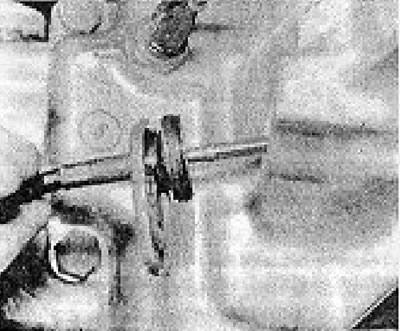
Photo 4V.31V....and pull out the speedometer cable.
32. Be careful not to lose the nylon pinion gear.
33. Disconnect the reverse light switch.
34. Remove all bolts securing the engine to the gearbox (the box will not fall until the rear cushion bolt is removed).
35. Insert a wooden block between the timing belt cover and the car body to prevent the engine from tilting when removing the gearbox.
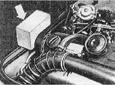
Figure 13.2. Insert a wooden block to prevent the engine from tilting (Section 4B).
36. Together with an assistant, support the gearbox and remove the rear mount bolt (see photo).
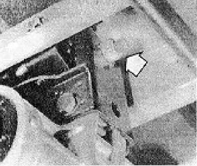
Photo 48.36. Rear gearbox mount bolt (shown by the arrow).
Move the gearbox back, making sure that it does not rest with all its weight on its drive shaft.
37. After the drive shaft of the gearbox disengages from the clutch, lower the gearbox to the ground.
38. Working at the top of the engine, disconnect the wire from the expansion tank of the cooling system.
39. Disconnect the expansion tank hoses from the engine (see photo).
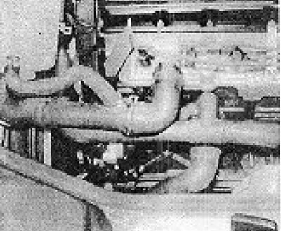
Photo 4B.39. Water hose connections to the engine.
Be prepared for some coolant to spill when doing this.
40. Unscrew the expansion tank mounting bolts and remove the tank together with the hoses.
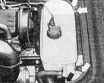
Figure 13.3. Expansion tank bolts (shown by arrows).
41. Disconnect the oil pressure sensor wire (see photo).
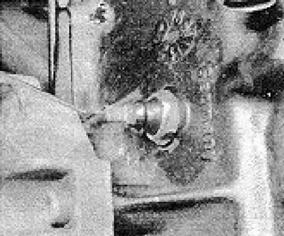
Photos 4B.41. Oil pressure sensor.
42. Disconnect the water hose at the rear of the cylinder head.
43. Disconnect the wires from the ignition coil.
44. Disconnect the spark plug wires and remove the distributor (see photo).
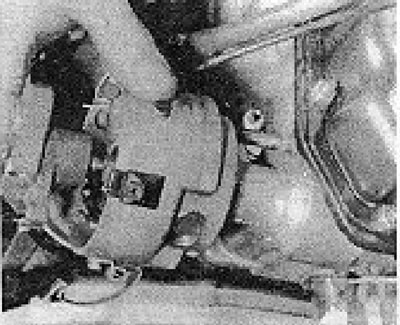
Photo 48.44. Removing the distributor.
45. Disconnect the coolant temperature sensor wire (see photo).
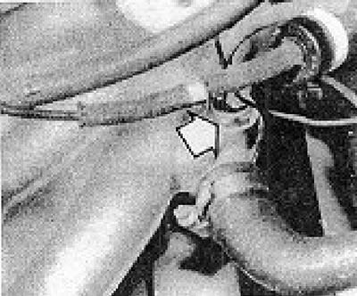
Photo 4B.45. Coolant temperature sensor (shown by the arrow).
46. Remove the nut securing the air intake elbow from the carburetor and disconnect the vacuum hoses from the hot air supply system control valve. Disconnect the other end of the air duct from the air cleaner.
47. Disconnect the hose from the breather valve (see photo) and remove the air duct.
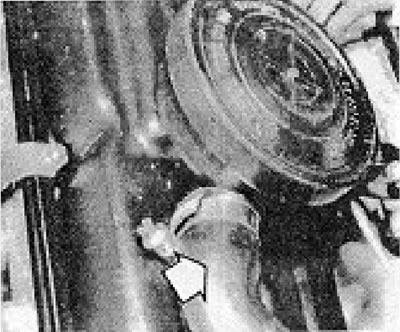
Photo 4B.47. Breather valve hose connection point (shown by the arrow).
48. Remove the breather valve (see photo), having a bayonet fit in the body.
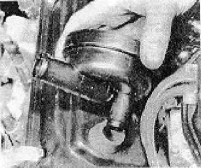
Photo 4B.48. Removing the breather valve.
49. Disconnect the water hose from the intake manifold.
50. Disconnect the inlet and outlet fuel pipes from the carburetor.
51. Disconnect the following wires: choke block covers; air bypass valve; collector heater; collector heater thermal switch.
52. The gas pedal cable has been removed (see photos).
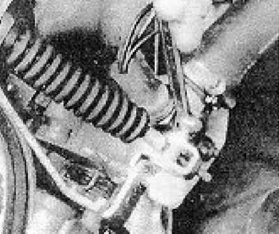
Photo 4B.52A. Disconnecting the gas pedal cable clamp...
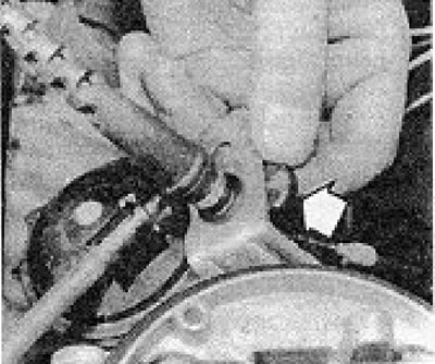
Photo 49.52B....and the clamp on the support bracket (shown by the arrow).
53. Disconnect the hot air supply hose from the air intake shield.
54. Disconnect the brake servo vacuum line (see photo).
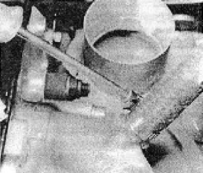
Photo 48.54. Disconnecting the brake servo vacuum hose.
55. Disconnect the remaining air hose from the intake manifold.
56. Disconnect the ground wire from the valve cover (see photo).
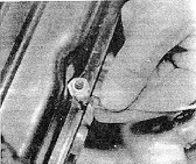
Photo 48.56. Disconnecting the valve cover ground wire.
57. Connect the hoists to the engine lifting eyes and lift it slightly.
58. Disconnect the right engine mount (see photo).
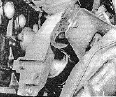
Photo 48.58 Spicy engine mount.
59. Disconnect the left engine mount (see photo).
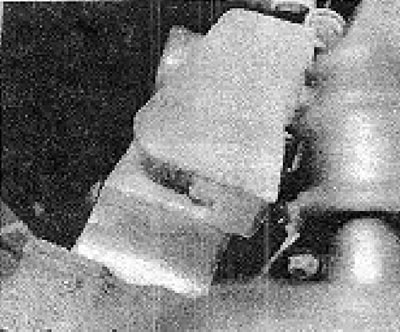
Photo 48.59. Left engine mount.
60. Slowly raise the engine, being careful not to damage the air bypass valve and ignition coil (see photo).
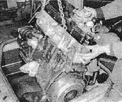
Photo 46.60. Raising the engine (pay attention to the position of the lifting ears).
61. Carefully remove the engine from the machine and place it on the ground or on a work bench.
Note: Due to the design of the oil pan, it is very difficult to install the engine upright, so it is recommended to first remove the oil pan and oil pickup tube.
62. Remove the remaining engine attachments.
63. Remove the intake manifold together with the carburetor.
64. Remove the exhaust manifold, paying attention to the position and fastening of the heat shields.
65. Remove the generator.
66. Remove the oil filter and, if necessary, the filter housing.
67. Unscrew the bolts and remove the thermostat housing and the thermostat itself.
68. Remove the clutch.
69. Removal of the remaining components is discussed in the following paragraphs on engine overhaul.
Visitor comments