



144. Remove the camshaft.
145. Before removing the valve mechanism parts, you should prepare clean boxes in which you can arrange the valve parts. Be careful not to confuse them.
146. Remove the pushers (see photo).
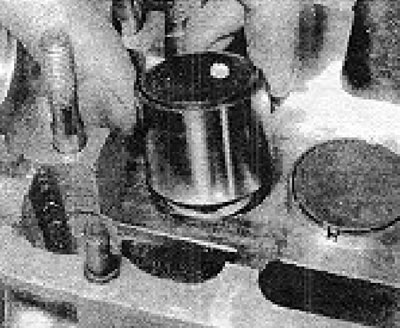
Photo 4B.146. Removing the pusher.
147. The procedure for removing the valves and rebuilding the cylinder head is the same as that described in Chapter 1, Section 18. Note the following points and refer to the 2.4L Engine Specifications.
148. The springs of both the intake and exhaust valves are located in their sockets (see photo).
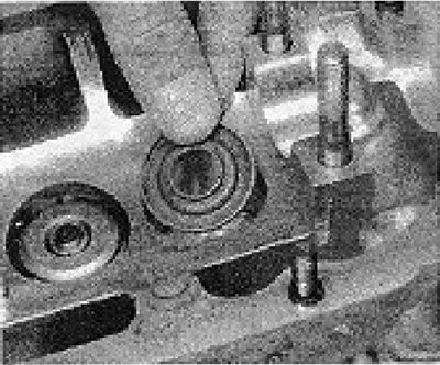
Photo 4B.148. Installing the valve spring seat.
149. The maximum dimensions for regrinding the head are shown in Figures 13.10 and 13.11 (see also chapter 1).
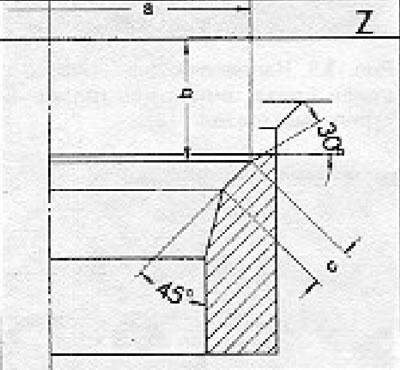
Figure 13.10. Regrinding of intake valve seats (section 4B).
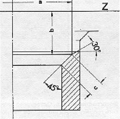
Figure 13.11. Regrinding of exhaust valve seats (section 4B).
150. Exhaust valves cannot be reground. They can only be rubbed in by hand.
151. Check that the oil spray holes are on the left/right axle (see photo).
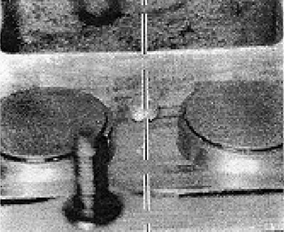
Photo 4B.151. Axis of oil spray holes.
152. After overhauling the cylinder head, the valve clearances should be checked and adjusted.
Visitor comments